I am doing a fair bit of work with operationally sensitive C code, so I decided to set up a Raspberry Pi Zero 2 W as a target for an embedded example, although please understand that many embedded targets greatly differ in how we need to handle them. Getting it running on the Pi with no operating system should validate enough of the properties that we can cross-compile, link, and load on most embedded systems (huge list of caveats here). They are cheap enough for people to afford if they wish to follow along, they are easier to get than STM32 or AVR microcontroller boards, and I can walk into Micro Center and buy one. Per person. Per day. Yeah, right, buddy. I've got friends for a reason.
The RPi Zero 2 W also works because my other boards are tied up on other projects, or as sacrificial targets for side-channel analysis. The Raspberry Pi ecosystem has boot firmware that we will reuse, leading to our own ARM64 startup assembly, eventually allowing us to run whatever arbitrary C program we would like.
This is also an attempt to inspire my uncle to forgo his corporate executive life and return to true, technical work. Little is more truly technical than mathematics on raw silicon hardware, and nothing is more exciting.
Alright, let's get started:
To prep the dev environment, we need to make sure we have access to a Linux box and the proper compiler toolchain. I will use the WSL2 partition on my laptop here. To prepare it with the needed toolchain:
sudo apt updatesudo apt install clang lld llvm make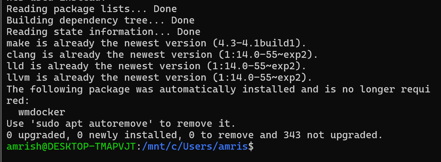
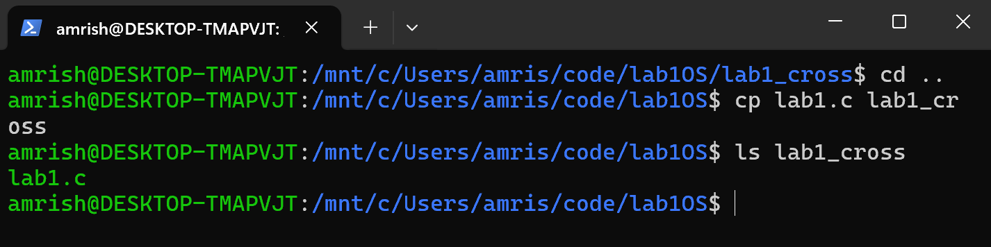
Alright, so first let's make sure we aren't pulling our hair out trying to get the simple things to work. We can start with boot.S, and just have it loop forever.
boot.S is the assembly we will be running on the bare metal. At a later point, we will use it to enter a control block in the C program.
.section .text.boot, "ax" //we need an executable code section .global _start //this is our entry point _start: mov x0, #42 //hello world without "Hello World!" hang: b hang //this label just branches to itself, infinitelyAlright, let's compile this:
clang --target=aarch64-none-elf -ffreestanding -c boot.S -o boot.o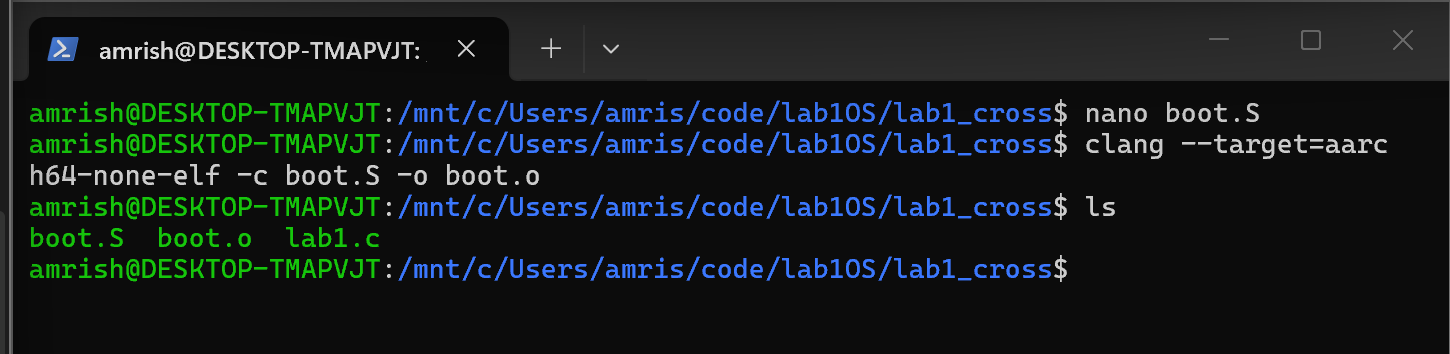
The --target=aarch64-none-elf option tells Clang to target bare-metal AArch64 using ELF (Executable and Linkable Format), with no OS in mind. ELF is not specific to Linux. Since we will do this bare metal, we can't count on OS-provided tools.
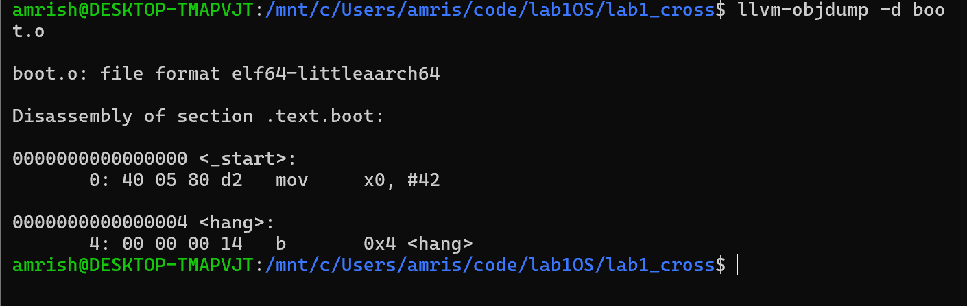
We can see we will move 42 into the x0 register, and branch forever on hang.

Now, we can see that start is at the 0x0 memory address, and 4 bytes later, we have our hang procedure. ARM64 instructions are 32 bits apiece. The object file has not been given the actual memory address. We need to translate this from starting at 0x0 in the boot.o to 0x80000 (and consequently 0x80004 for hang). The Raspberry Pi Zero 2 W, in 64-bit mode, loads its kernel8.img at 0x80000.
nano linker.ldFor our linker file, we need to say where the different portions of the program will be.
.text is where we put executable instructions.
.rodata is where there is read-only data.
.data is for initialized but writable variables.
.bss is for uninitialized or zero-initialized variables.
. = is a special linker variable, the location counter. Here we will tell it to place the rest of the data in memory, starting at 0x80000.
ENTRY(_start) /* we declare where we want to start*/ SECTIONS { /*beginning memory address*/ . = 0x80000; /*our text section*/ .text : { KEEP(*(.text.boot)) /*rest of exe code */ *(.text*) }}(Note that hang is not separate; it just gives the procedure following it an address we can reference from elsewhere.)
Now we need a stack. An obviously infallible, hard-to-get-wrong construct. If it wasn't, people would be smashing it for fun and/or profit. First, we need to initialize our stack pointer. Stacks grow downward, towards lower memory addresses, so we need to allocate high and go down. If we want 4096 bytes, we need to go from, for example, 0x91000 to 0x90000. Why not 0x90FFF?
stack_pointer = 0x91000 - 0x10 = 0x90ff0
Also, on ARM64, the stack pointer has to be 16-byte aligned when it's used to access memory.
So now we need to modify boot.S to load in our proper stack pointer. ARM64 does not let us load random 64-bit addresses into the stack pointer with mov. We need to ldr the address of the stack top into x0, and mov x0 into the stack pointer.
In linker.ld:
ENTRY(_start) /* we declare where we want to start*/ SECTIONS { /*beginning memory address*/ . = 0x80000; /*our text section*/ .text : { KEEP(*(.text.boot)) /*rest of exe code */ *(.text*) } .stack (NOLOAD): { . = ALIGN(16); /* save the address*/ __stack_bottom = .; . += 4096; /*push it 4kb*/ __stack_top = .; /*snag that thang again. now we have the top and bottom *to reference*/ } } ENTRY(_start) /* we declare where we want to start*/ SECTIONS { /*beginning memory address*/ . = 0x80000; /*our text section*/ .text : { KEEP(*(.text.boot)) /*rest of exe code */ *(.text*) } .stack (NOLOAD): { . = ALIGN(16); /* save the address*/ __stack_bottom = .; . += 4096; /*push it 4kb*/ __stack_top = .; /*snag that thang again. now we have the top and bottom *to reference*/ } }Alright, now let's rebuild.
clang --target=aarch64-none-elf -ffreestanding -c boot.S -o boot.o ld.lld -m aarch64elf -T linker.ld -o kernel8.elf boot.o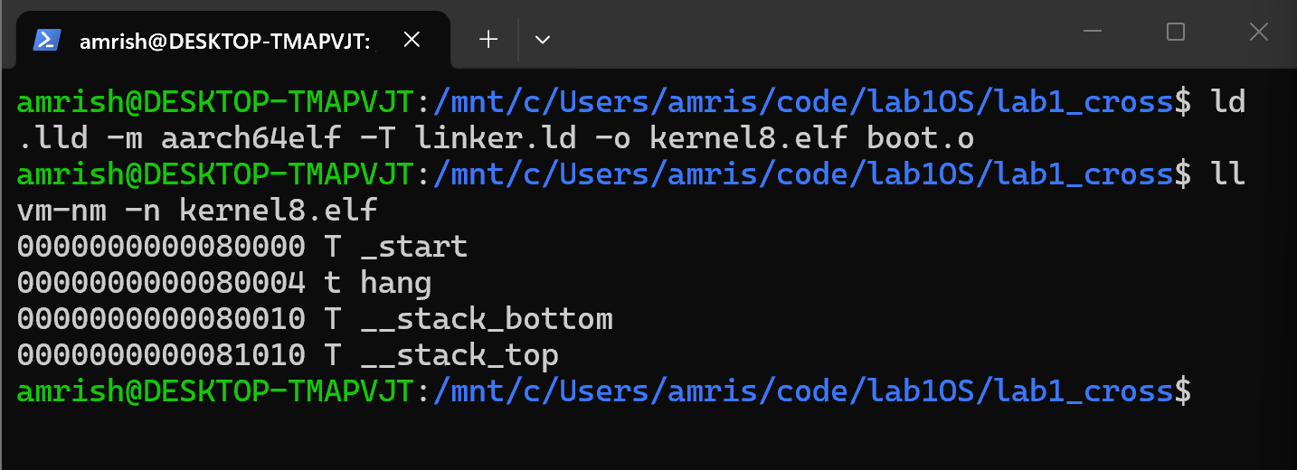
If we look at the addresses, we can see things are where we expect them to be.
Let's initialize the stack in our assembly.
.section .text.boot, "ax" //we need an executable code section .global _start //this is our entry point _start: ldr x0, =__stack_top mov sp, x0 mov x0, #42 //hello world without "Hello World!"hang: b hang //this label just branches to itself, infinitely.section .text.boot, "ax" //we need an executable code section .global _start //this is our entry point _start: ldr x0, =__stack_top mov sp, x0 mov x0, #42 //hello world without "Hello World!" hang: b hang //this label just branches to itself, infinitely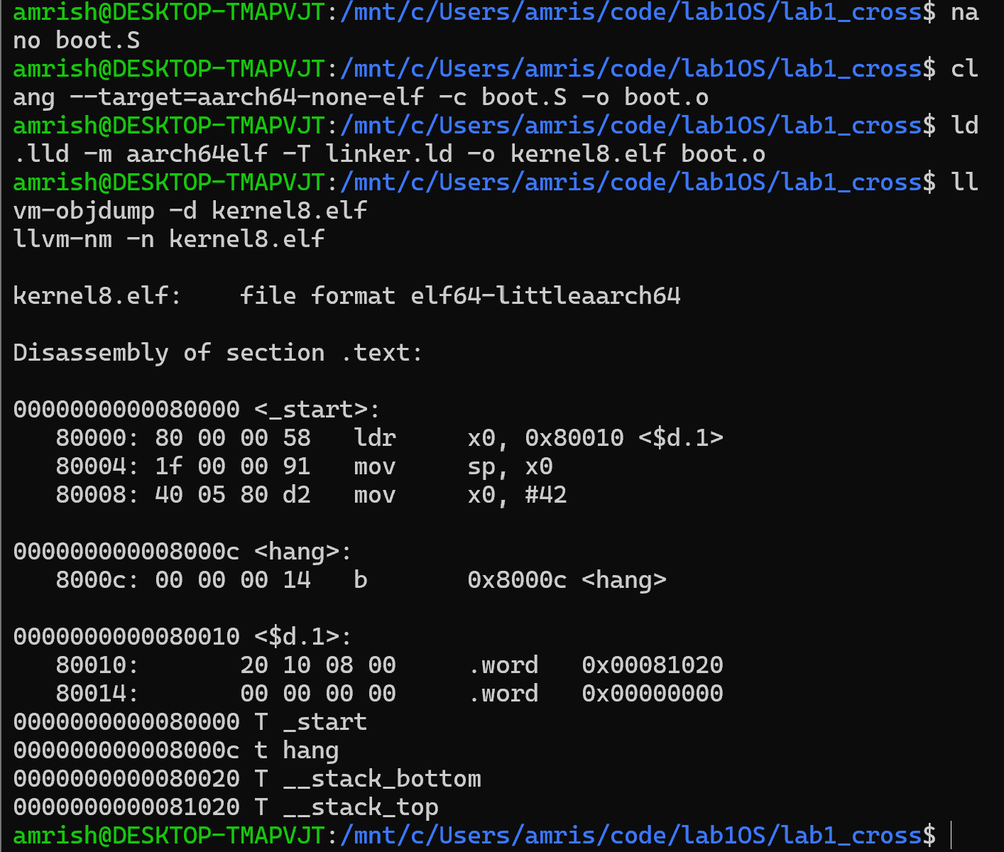
Rebuilding and examining, we can see we have a start that initializes a 4 KB stack for us, a hang procedure, and the addresses for the stack top and bottom somewhere we can reference them. The reason we did not hardcode the stack is we don't want to have to remember it after each change we make. We load up all the executable code, and then we allocate 4096 bytes from whatever that point is. If we forget, we could write somewhere we don't mean to. This is colloquially known as a "fireable offense".
Now, this Pi has four Cortex-A53 cores. Each has its own registers, one of which will be the stack pointer. We don't want four physical cores pointing at the same address. That could lead to headaches, hair pulling, and tears. Right now, we want to constrain ourselves to one core to make this simple. Thankfully, ARM64 was architected well, and we have the Multiprocessor Affinity Register. Dead serious. `MPIDR` or `MPIDR_EL1`. Don't ask me who names this shit. Anyways, there is a useful instruction, mrs, that we can use to read the affinity into a register:
mrs x1, mpidr_el1
This loads it into x1. So let's add that to our program.
In boot.S:
.section .text.boot, "ax" //we need an executable code section .global _start //this is our entry point _start: //we should do this before initializing the stack mrs x1, mpidr_el1 and x1, x1, #0xFF //we want the lowest 8 bits cbnz x1, hang //end this kid's career if he isn't 0 ldr x0, =__stack_top mov sp, x0 mov x0, #42 //hello world without "Hello World!" hang: b hang //this label just branches to itself, infinitely.section .text.boot, "ax" //we need an executable code section .global _start //this is our entry point _start: //we should do this before initializing the stack mrs x1, mpidr_el1 and x1, x1, #0xFF //we want the lowest 8 bits cbnz x1, hang //end this kid's career if he isn't 0 ldr x0, =__stack_top mov sp, x0 mov x0, #42 //hello world without "Hello World!" hang: b hang //this label just branches to itself, infinitelyFor each core that is not core 0, we hang it. Or send it to the hang procedure, whichever wording is better.
Alright, we should roughly be ready to execute C. Let's make a small token C program.
void kernel_main(unsigned long inital_value){volatile unsigned long counter = inital_value; while (1){ counter++; }}If volatile is unfamiliar, it's basically a descriptor we use to tell the compiler it's not allowed to decide we don't need it. Compilers have a really annoying habit of deciding that zeroing out registers containing sensitive information, or initializing them to values we will overwrite before we read them (constant-time properties) are unnecessary, introducing our enemies to our data. That makes compilers a point of failure that needs to be considered in your engineering model. You should ALWAYS read and consider the actual properties of output assembly. You should never blindly trust tools, because they are pieces of logic put together by other people, with their use case, safety bounds, and intentions codified. In critical infrastructure, this can literally kill someone. Never, ever blindly trust tools.
Now let's get our assembly pointing at kernel_main.
In boot.S:
.section .text.boot, "ax" //we need an executable code section .global _start //this is our entry point _start: //we should do this before initializing the stack mrs x1, mpidr_el1 and x1, x1, #0xFF //we want the lowest 8 bits cbnz x1, hang //end this kid's career if he isn't 0 ldr x0, =__stack_top mov sp, x0 mov x0, #42 //hello world without "Hello World!" bl kernel_main //branch with link to kernel main hang: b hang //this label just branches to itself, infinitely.section .text.boot, "ax" //we need an executable code section .global _start //this is our entry point _start: //we should do this before initializing the stack mrs x1, mpidr_el1 and x1, x1, #0xFF //we want the lowest 8 bits cbnz x1, hang //end this kid's career if he isn't 0 ldr x0, =__stack_top mov sp, x0 mov x0, #42 //hello world without "Hello World!" bl kernel_main //branch with link to kernel main hang: b hang //this label just branches to itself, infinitely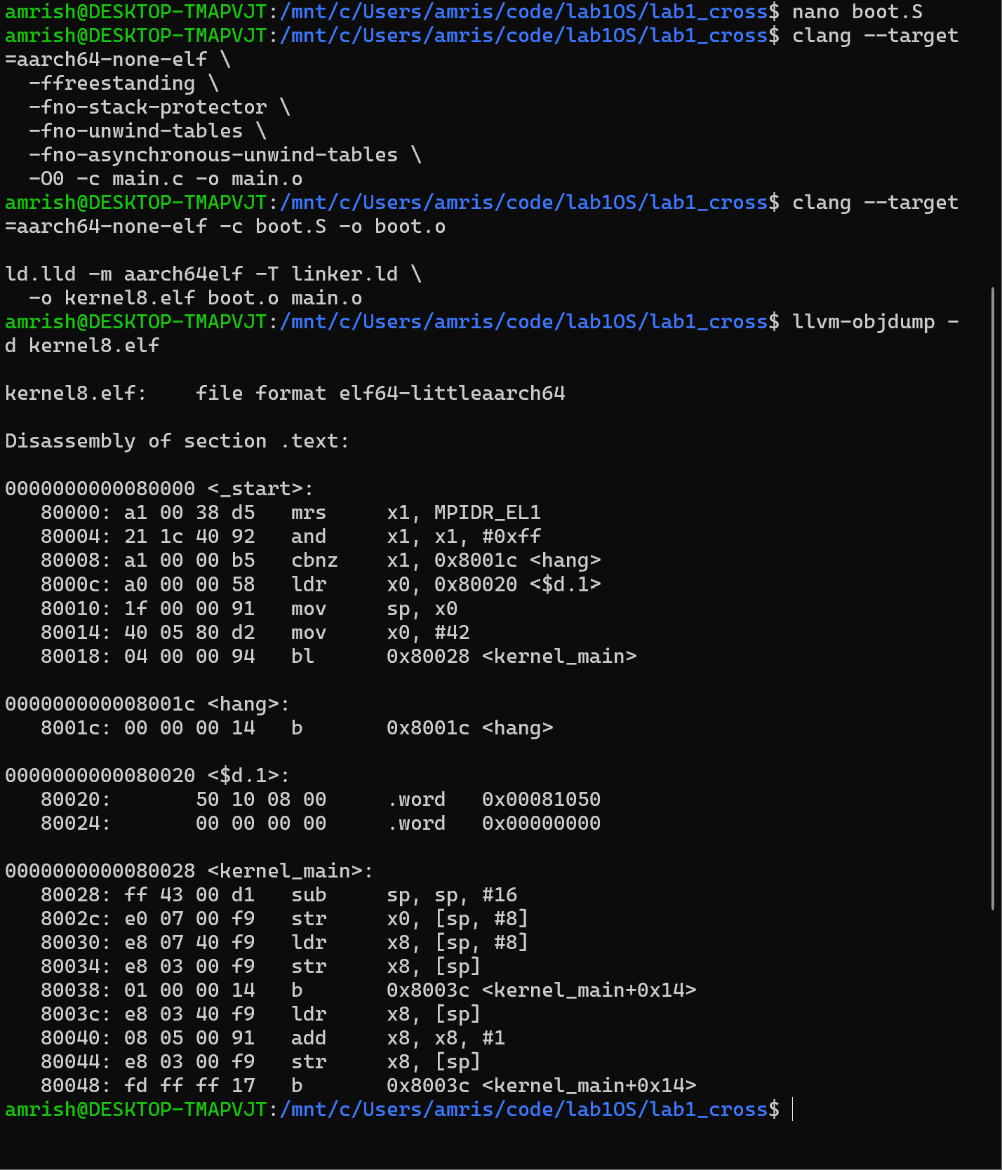
Okay, perfect, we can see the C function is compiled in. Let's take a quick second to look at it side by side with the C code.
void kernel_main(unsigned long inital_value) //inital_value in x0{//sub sp, sp, #16 -> move 16 bytes down the stack, moving sp down//str x0, [sp, #8] -> stores 42 at sp+8//ldr x8, [sp, #8] -> loads 42 from memory at sp+8 into x8//str x8, [sp] -> x8 into stack memory volatile unsigned long counter = inital_value; //stored on stack while (1){ //<kernel_main+0x14> jumps to here counter++; //load value from stack into x8 add 1 to x8, store //x8 in stack memory }}void kernel_main(unsigned long inital_value)void kernel_main(unsigned long inital_value) //inital_value in x0{volatile unsigned long counter = inital_value;//sub sp, sp, #16 -> move 16 bytes down the stack, moving sp down//str x0, [sp, #8] -> stores 42 at sp+8//ldr x8, [sp, #8] -> loads 42 from memory at sp+8 into x8//str x8, [sp] -> x8 into stack memory while (1){ counter++;volatile unsigned long counter = inital_value; //stored on stack while (1){ //<kernel_main+0x14> jumps to here counter++; //load value from stack into x8 add 1 to x8, store //x8 in stack memory }}
Now, in ARM64, we expect the initial value to be in x0. If we put 42 into x0, kernel_main receives 42.
x0 is the first argument.
x1 is second.
x2 is third.
x_n is next.
x7 is eighth.
Alright, so we have our rough bootstrapping down, and we can handle memory-mapped I/O to the actual Pi. Let's define our UART configuration.
nano uart.cFor the Pi, the GPIO base is at 0x3F200000. GPFSEL1 is the register controlling GPIO pins 10-19, with each pin being assigned 3 bits.
We will use selector &= to clear the function selection bits in GPIO14 and 15.
And selector |= to set the fields to 010.
#include <stdint.h> #define GPIO_BASE 0x3F200000UL#define GPFSEL1 (GPIO_BASE + 0x04UL) static uint32_t mmio_read32(uintptr_t address){ return *(volatile uint32_t *)address;} static void mmio_write32(uintptr_t address, uint32_t value){ *(volatile uint32_t *)address = value; } void gpio_uart_pins(void){ uint32_t selector = mmio_read32(GPFSEL1); selector &= ~((7U << 12) | (7U << 15)); selector |= (2u << 12) | (2u << 15); mmio_write32(GPFSEL1, selector);} clang --target=aarch64-none-elf -ffreestanding -O0 -c uart.c -o uart.o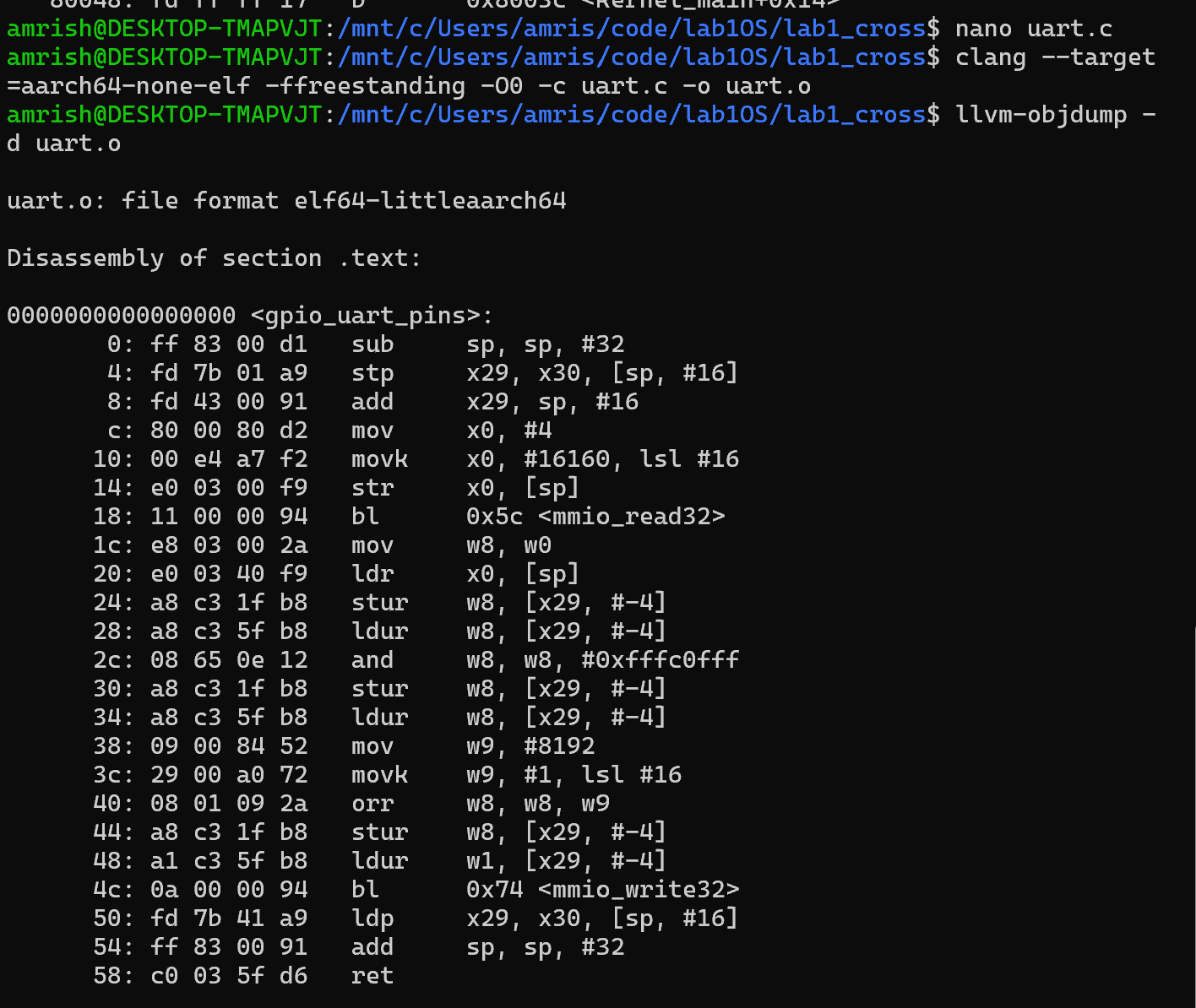
We can see the 32 bytes of stack allocation, the branching to the read and write functions, and the reset of the stack. Perfect.
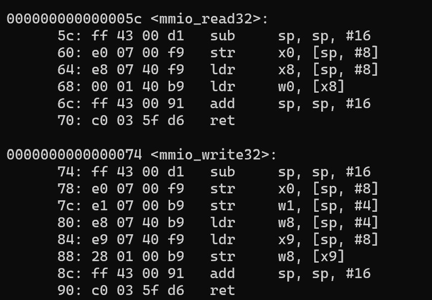
And we can see reading and writing to the hardware registers.
68: 00 01 40 b9 ldr w0, [x8] and in mmio_write32 88: str w8, [x9]Now we need to enable mini UART.
The auxiliary peripheral register block starts at 0x3F215000.
Now in uart.c:
#include <stdint.h> #define AUX_BASE 0x3F215000UL#define AUX_ENABLES (AUX_BASE + 0X04UL) //enable mini UART#define AUX_MU_CNTL (AUX_BASE +0X60UL) //lever for tx and rx #define GPIO_BASE 0x3F200000UL#define GPFSEL1 (GPIO_BASE + 0x04UL) static uint32_t mmio_read32(uintptr_t address){ return *(volatile uint32_t *)address;} static void mmio_write32(uintptr_t address, uint32_t value){ *(volatile uint32_t *)address = value; } void gpio_uart_pins(void){ uint32_t selector = mmio_read32(GPFSEL1); selector &= ~((7U << 12) | (7U << 15)); selector |= (2u << 12) | (2u << 15); mmio_write32(GPFSEL1, selector);} void mini_uart_enable(void){ uint32_t value = mmio_read32(AUX_ENABLES); value |= (1u << 0); mmio_write32(AUX_ENABLES, value); mmio_write32(AUX_MU_CNTL,0U); }#include <stdint.h> #define AUX_BASE 0x3F215000UL#define AUX_ENABLES (AUX_BASE + 0X04UL) //enable mini UART#define AUX_MU_CNTL (AUX_BASE +0X60UL) //lever for tx and rx #define GPIO_BASE 0x3F200000UL#define GPFSEL1 (GPIO_BASE + 0x04UL) static uint32_t mmio_read32(uintptr_t address){ return *(volatile uint32_t *)address;} static void mmio_write32(uintptr_t address, uint32_t value){ *(volatile uint32_t *)address = value; } void gpio_uart_pins(void){ uint32_t selector = mmio_read32(GPFSEL1); selector &= ~((7U << 12) | (7U << 15)); selector |= (2u << 12) | (2u << 15); mmio_write32(GPFSEL1, selector);} void mini_uart_enable(void){ uint32_t value = mmio_read32(AUX_ENABLES); value |= (1u << 0); mmio_write32(AUX_ENABLES, value); mmio_write32(AUX_MU_CNTL,0U); }Now we need to tell the hardware how many bits we want in a character and at what rate we want our bits transmitted.
#include <stdint.h> #define AUX_MU_LCR (AUX_BASE + 0x4CUL) //8-bit characters#define AUX_MU_BAUD (AUX_BASE + 0x68UL) // 115200 baud rate#define AUX_BASE 0x3F215000UL#define AUX_ENABLES (AUX_BASE + 0X04UL) //enable mini UART#define AUX_MU_CNTL (AUX_BASE +0X60UL) //lever for tx and rx #define GPIO_BASE 0x3F200000UL#define GPFSEL1 (GPIO_BASE + 0x04UL) static uint32_t mmio_read32(uintptr_t address){ return *(volatile uint32_t *)address;} static void mmio_write32(uintptr_t address, uint32_t value){ *(volatile uint32_t *)address = value; } void gpio_uart_pins(void){ uint32_t selector = mmio_read32(GPFSEL1); selector &= ~((7U << 12) | (7U << 15)); selector |= (2u << 12) | (2u << 15); mmio_write32(GPFSEL1, selector);} void mini_uart_enable(void){ uint32_t value = mmio_read32(AUX_ENABLES); value |= (1u << 0); mmio_write32(AUX_ENABLES, value); mmio_write32(AUX_MU_CNTL,0U); } #include <stdint.h> #define AUX_MU_LCR (AUX_BASE + 0x4CUL) //8-bit characters#define AUX_MU_BAUD (AUX_BASE + 0x68UL) // 115200 baud rate#define AUX_BASE 0x3F215000UL#define AUX_ENABLES (AUX_BASE + 0X04UL) //enable mini UART#define AUX_MU_CNTL (AUX_BASE +0X60UL) //lever for tx and rx #define GPIO_BASE 0x3F200000UL#define GPFSEL1 (GPIO_BASE + 0x04UL) static uint32_t mmio_read32(uintptr_t address){ return *(volatile uint32_t *)address;} static void mmio_write32(uintptr_t address, uint32_t value){ *(volatile uint32_t *)address = value; } void gpio_uart_pins(void){ uint32_t selector = mmio_read32(GPFSEL1); selector &= ~((7U << 12) | (7U << 15)); selector |= (2u << 12) | (2u << 15); mmio_write32(GPFSEL1, selector);} void mini_uart_enable(void){ uint32_t value = mmio_read32(AUX_ENABLES); value |= (1u << 0); mmio_write32(AUX_ENABLES, value); mmio_write32(AUX_MU_CNTL,0U); }Baud rate is (core clock)/(8(divisor+1))
Alright, let's say we want the Pi's clock at 250 MHz.
Divisor = ((250,000,000)/(8(115200))) - 1
Which is roughly 270.
This will actually give us a baud rate of 115,314, which is fine for right now.
We also need to define a small set of configuration options, so the Pi knows what formats we intend to use.
#include <stdint.h> #define AUX_BASE 0x3F215000UL#define AUX_MU_LCR (AUX_BASE + 0x4CUL) //8-bit characters#define AUX_MU_BAUD (AUX_BASE + 0x68UL) // 115200 baud rate#define AUX_ENABLES (AUX_BASE + 0X04UL) //enable mini UART#define AUX_MU_CNTL (AUX_BASE +0X60UL) //lever for tx and rx#define AUX_MU_IER (AUX_BASE + 0x44UL) //interrupt enable#define AUX_MU_IIR (AUX_BASE + 0x48UL) //FIFO control#define AUX_MU_MCR (AUX_BASE + 0x50UL) //modem control #define GPIO_BASE 0x3F200000UL#define GPFSEL1 (GPIO_BASE + 0x04UL) static uint32_t mmio_read32(uintptr_t address){ return *(volatile uint32_t *)address;} static void mmio_write32(uintptr_t address, uint32_t value){ *(volatile uint32_t *)address = value; } void gpio_uart_pins(void){ uint32_t selector = mmio_read32(GPFSEL1); selector &= ~((7U << 12) | (7U << 15)); selector |= (2u << 12) | (2u << 15); mmio_write32(GPFSEL1, selector);} void mini_uart_enable(void){ uint32_t value = mmio_read32(AUX_ENABLES); value |= (1u << 0); mmio_write32(AUX_ENABLES, value); mmio_write32(AUX_MU_CNTL,0U); } void mini_uart_configure(void){ mmio_write32(AUX_MU_LCR, 3u); //write the 8-bit mode mmio_write32(AUX_MU_BAUD, 270u); //set the baud to 115200 @ 250 MHz //we're gonna poll instead of using interrupts mmio_write32(AUX_MU_IER, 0u); //no UART interrupts mmio_write32(AUX_MU_MCR, 0u); //no modem mmio_write32(AUX_MU_IIR, 6u); //clear all the rx tx FIFOs } #include <stdint.h> #define AUX_BASE 0x3F215000UL#define AUX_MU_LCR (AUX_BASE + 0x4CUL) //8-bit characters#define AUX_MU_BAUD (AUX_BASE + 0x68UL) // 115200 baud rate#define AUX_BASE 0x3F215000UL#define AUX_ENABLES (AUX_BASE + 0X04UL) //enable mini UART#define AUX_MU_CNTL (AUX_BASE +0X60UL) //lever for tx and rx#define AUX_MU_IER (AUX_BASE + 0x44UL) //interrupt enable#define AUX_MU_IIR (AUX_BASE + 0x48UL) //FIFO control#define AUX_MU_MCR (AUX_BASE + 0x50UL) //modem control #define GPIO_BASE 0x3F200000UL#define GPFSEL1 (GPIO_BASE + 0x04UL) static uint32_t mmio_read32(uintptr_t address){ return *(volatile uint32_t *)address;} static void mmio_write32(uintptr_t address, uint32_t value){ *(volatile uint32_t *)address = value; } void gpio_uart_pins(void){ uint32_t selector = mmio_read32(GPFSEL1); selector &= ~((7U << 12) | (7U << 15)); selector |= (2u << 12) | (2u << 15); mmio_write32(GPFSEL1, selector);} void mini_uart_enable(void){ uint32_t value = mmio_read32(AUX_ENABLES); value |= (1u << 0); mmio_write32(AUX_ENABLES, value); mmio_write32(AUX_MU_CNTL,0U); } void mini_uart_configure(void){ mmio_write32(AUX_MU_LCR, 3u); //write the 8-bit mode mmio_write32(AUX_MU_BAUD, 270u); //set the baud to 115200 @ 250 MHz //we're gonna poll instead of using interrupts mmio_write32(AUX_MU_IER, 0u); //no UART interrupts mmio_write32(AUX_MU_MCR, 0u); //no modem mmio_write32(AUX_MU_IIR, 6u); //clear all the rx tx FIFOs } Alright, let's make sure our nano machinations match what Clang thinks is sane.
clang --target=aarch64-none-elf -ffreestanding -O0 -c uart.c -o uart.o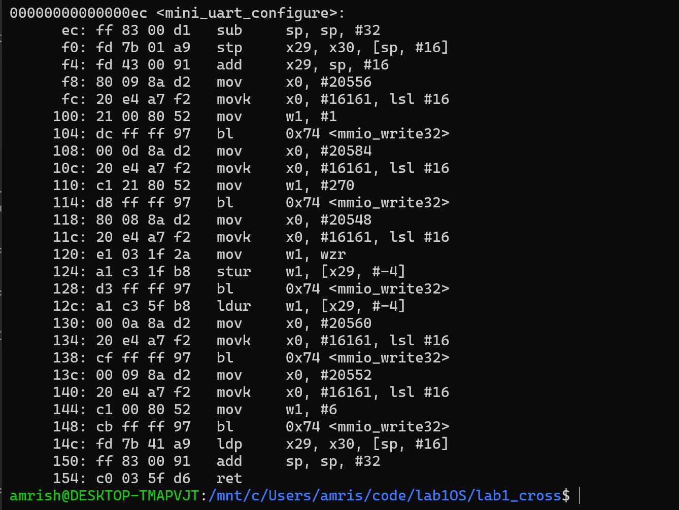
Okay, now that we have recompiled, and the compiler-generated assembly looks good, we need to configure the GPIO pull resistors. The Pi uses GPPUD and GPPUDCLK0 for configuring its pull-up and pull-down resistors.
It is likely we will need to induce a short delay between some of our register writes. It is small enough we shouldn't make the boot sequence a pain or anything, but it's worth keeping as small as possible. We will introduce a void function that simply loops NOP assembly instructions. We will need it to be volatile because a compiler will likely see this as wasteful. It's not wrong... just contextually unfortunate. As compilers often are.
#include <stdint.h> #define AUX_BASE 0x3F215000UL#define AUX_MU_LCR (AUX_BASE + 0x4CUL) //8-bit characters#define AUX_MU_BAUD (AUX_BASE + 0x68UL) // 115200 baud rate#define AUX_ENABLES (AUX_BASE + 0X04UL) //enable mini UART#define AUX_MU_CNTL (AUX_BASE +0X60UL) //lever for tx and rx#define AUX_MU_IER (AUX_BASE + 0x44UL) //interrupt enable#define AUX_MU_IIR (AUX_BASE + 0x48UL) //FIFO control#define AUX_MU_MCR (AUX_BASE + 0x50UL) //modem control#define AUX_MU_IO (AUX_BASE + 0x40UL) // data register, sends to tx FIFO#define AUX_MU_LSR (AUX_BASE + 0x54UL) //line status register #define GPIO_BASE 0x3F200000UL#define GPFSEL1 (GPIO_BASE + 0x04UL)#define GPPUD (GPIO_BASE + 0x94UL)#define GPPUDCLK0 (GPIO_BASE + 0x98UL) static uint32_t mmio_read32(uintptr_t address){ return *(volatile uint32_t *)address;} static void mmio_write32(uintptr_t address, uint32_t value){ *(volatile uint32_t *)address = value; } void gpio_uart_pins(void){ uint32_t selector = mmio_read32(GPFSEL1); selector &= ~((7U << 12) | (7U << 15)); selector |= (2u << 12) | (2u << 15); mmio_write32(GPFSEL1, selector);} void mini_uart_enable(void){ uint32_t value = mmio_read32(AUX_ENABLES); value |= (1u << 0); mmio_write32(AUX_ENABLES, value); mmio_write32(AUX_MU_CNTL,0U); } void mini_uart_configure(void){ mmio_write32(AUX_MU_LCR, 3u); //write the 8-bit mode mmio_write32(AUX_MU_BAUD, 270u); //set the baud to 115200 @ 250 MHz //we're gonna poll instead of using interrupts mmio_write32(AUX_MU_IER, 0u); //no UART interrupts mmio_write32(AUX_MU_MCR, 0u); //no modem mmio_write32(AUX_MU_IIR, 6u); //clear all the rx tx FIFOs } static void delay_cycles(void){ for (volatile unsigned i = 0; i < 200; i++) { __asm__ volatile("nop"); }} void gpio_uart_disable_pulls(void){ mmio_write32(GPPUD, 0u); //disable pull-up and pull-down resistors delay_cycles(); //add our 200 nops mmio_write32(GPPUDCLK0, (1u << 14) | (1u << 15)); //configure GPIO 14 and 15 delay_cycles(); mmio_write32(GPPUD, 0u); //Clear control reg mmio_write32(GPPUDCLK0, 0u); //clear clock reg} void uart_putc(char c){ while ((mmio_read32(AUX_MU_LSR) & (1u << 5)) == 0u) { } //just continuously polling until it's ready mmio_write32(AUX_MU_IO, (uint8_t)c); //send the character, cast to 8 bit uint} //this is effectively our printf alternativevoid uart_puts(const char *str){ while (*str != '\0') { uart_putc(*str); str++; }} //now we need an initialization function void uart_init(void){ mini_uart_enable(); mini_uart_configure(); gpio_uart_disable_pulls(); gpio_uart_pins(); mmio_write32(AUX_MU_CNTL, 3u); //enable tx and rx} #include <stdint.h> #define AUX_BASE 0x3F215000UL#define AUX_MU_LCR (AUX_BASE + 0x4CUL) //8-bit characters#define AUX_MU_BAUD (AUX_BASE + 0x68UL) // 115200 baud rate#define AUX_ENABLES (AUX_BASE + 0X04UL) //enable mini UART#define AUX_MU_CNTL (AUX_BASE +0X60UL) //lever for tx and rx#define AUX_MU_IER (AUX_BASE + 0x44UL) //interrupt enable#define AUX_MU_IIR (AUX_BASE + 0x48UL) //FIFO control#define AUX_MU_MCR (AUX_BASE + 0x50UL) //modem control#define AUX_MU_IO (AUX_BASE + 0x40UL) // data register, sends to tx FIFO#define AUX_MU_LSR (AUX_BASE + 0x54UL) //line status register #define GPIO_BASE 0x3F200000UL#define GPFSEL1 (GPIO_BASE + 0x04UL)#define GPPUD (GPIO_BASE + 0x94UL)#define GPPUDCLK0 (GPIO_BASE + 0x98UL) static uint32_t mmio_read32(uintptr_t address){ return *(volatile uint32_t *)address;} static void mmio_write32(uintptr_t address, uint32_t value){ *(volatile uint32_t *)address = value; } void gpio_uart_pins(void){ uint32_t selector = mmio_read32(GPFSEL1); selector &= ~((7U << 12) | (7U << 15)); selector |= (2u << 12) | (2u << 15); mmio_write32(GPFSEL1, selector);} void mini_uart_enable(void){ uint32_t value = mmio_read32(AUX_ENABLES); value |= (1u << 0); mmio_write32(AUX_ENABLES, value); mmio_write32(AUX_MU_CNTL,0U); } void mini_uart_configure(void){ mmio_write32(AUX_MU_LCR, 3u); //write the 8-bit mode mmio_write32(AUX_MU_BAUD, 270u); //set the baud to 115200 @ 250 MHz //we're gonna poll instead of using interrupts mmio_write32(AUX_MU_IER, 0u); //no UART interrupts mmio_write32(AUX_MU_MCR, 0u); //no modem mmio_write32(AUX_MU_IIR, 6u); //clear all the rx tx FIFOs } static void delay_cycles(void){ for (volatile unsigned i = 0; i < 200; i++) { __asm__ volatile("nop"); }} void gpio_uart_disable_pulls(void){ mmio_write32(GPPUD, 0u); //disable pull-up and pull-down resistors delay_cycles(); //add our 200 nops mmio_write32(GPPUDCLK0, (1u << 14) | (1u << 15)); //configure GPIO 14 and 15 delay_cycles(); mmio_write32(GPPUD, 0u); //Clear control reg mmio_write32(GPPUDCLK0, 0u); //clear clock reg} void uart_putc(char c){ while ((mmio_read32(AUX_MU_LSR) & (1u << 5)) == 0u) { } //just continuously polling until it's ready mmio_write32(AUX_MU_IO, (uint8_t)c); //send the character, cast to 8 bit uint} //this is effectively our printf alternativevoid uart_puts(const char *str){ while (*str != '\0') { uart_putc(*str); str++; }} //now we need an initialization function void uart_init(void){ mini_uart_enable(); mini_uart_configure(); gpio_uart_disable_pulls(); gpio_uart_pins(); mmio_write32(AUX_MU_CNTL, 3u); //enable tx and rx}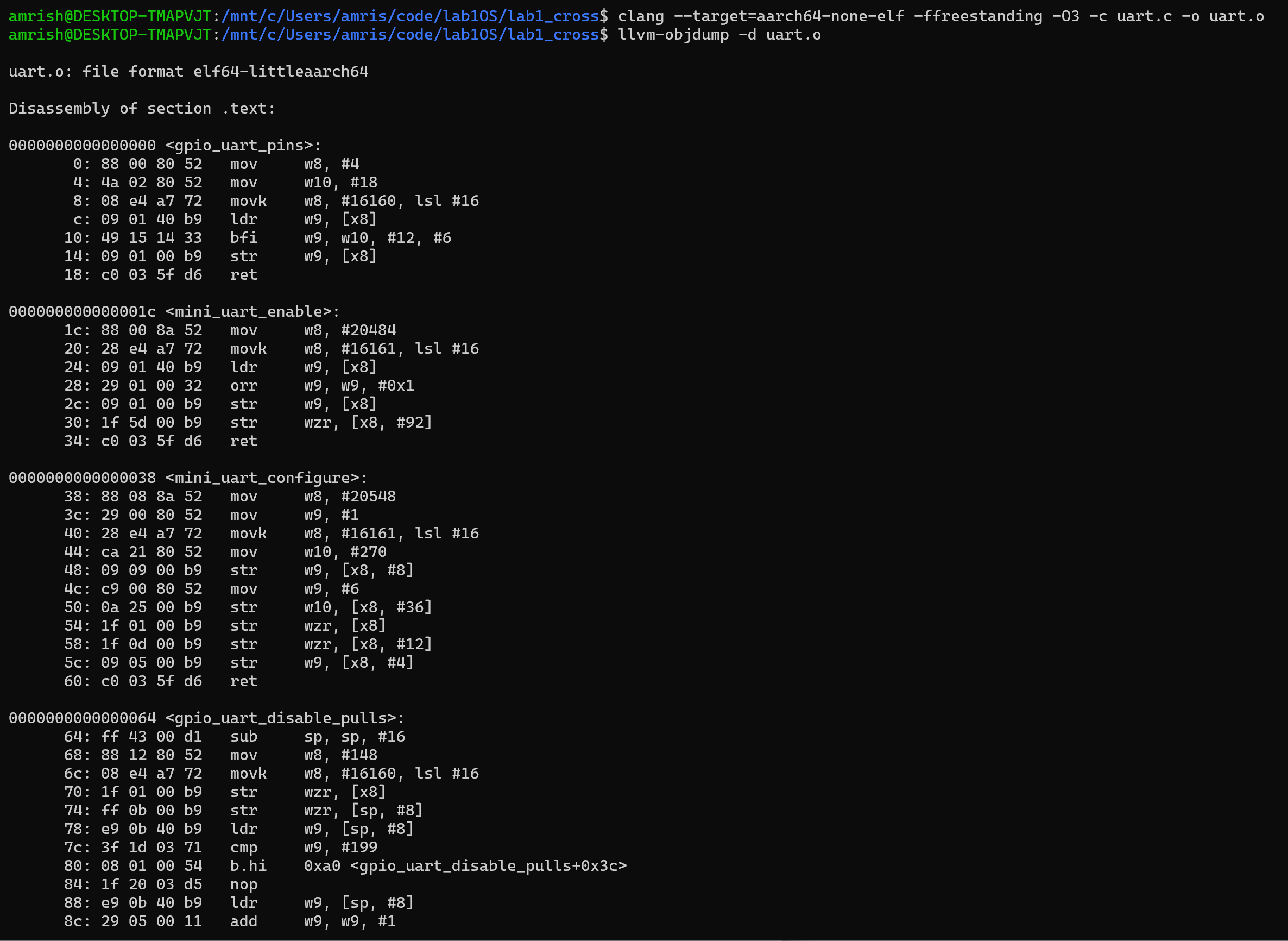
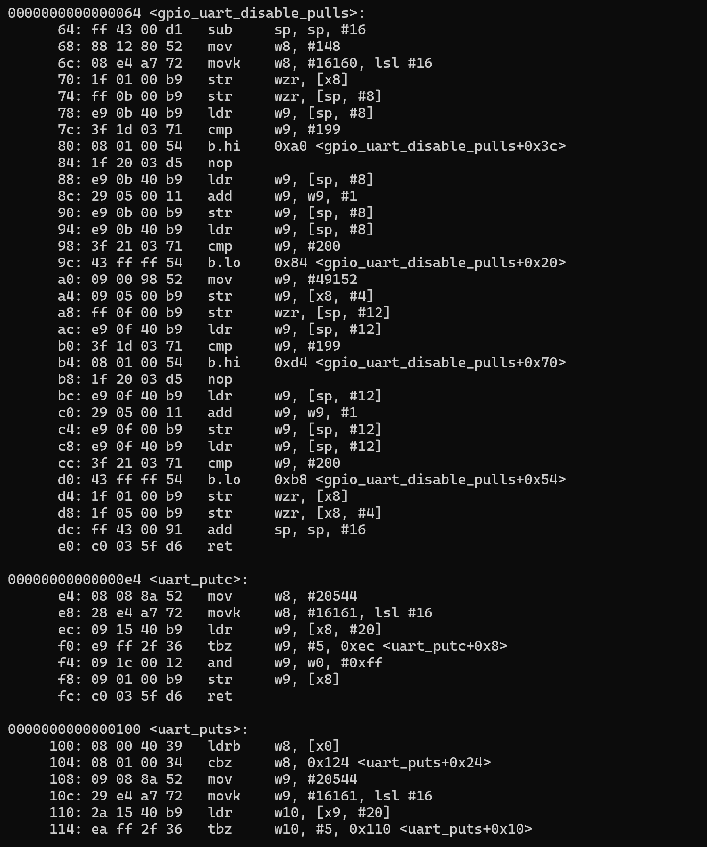
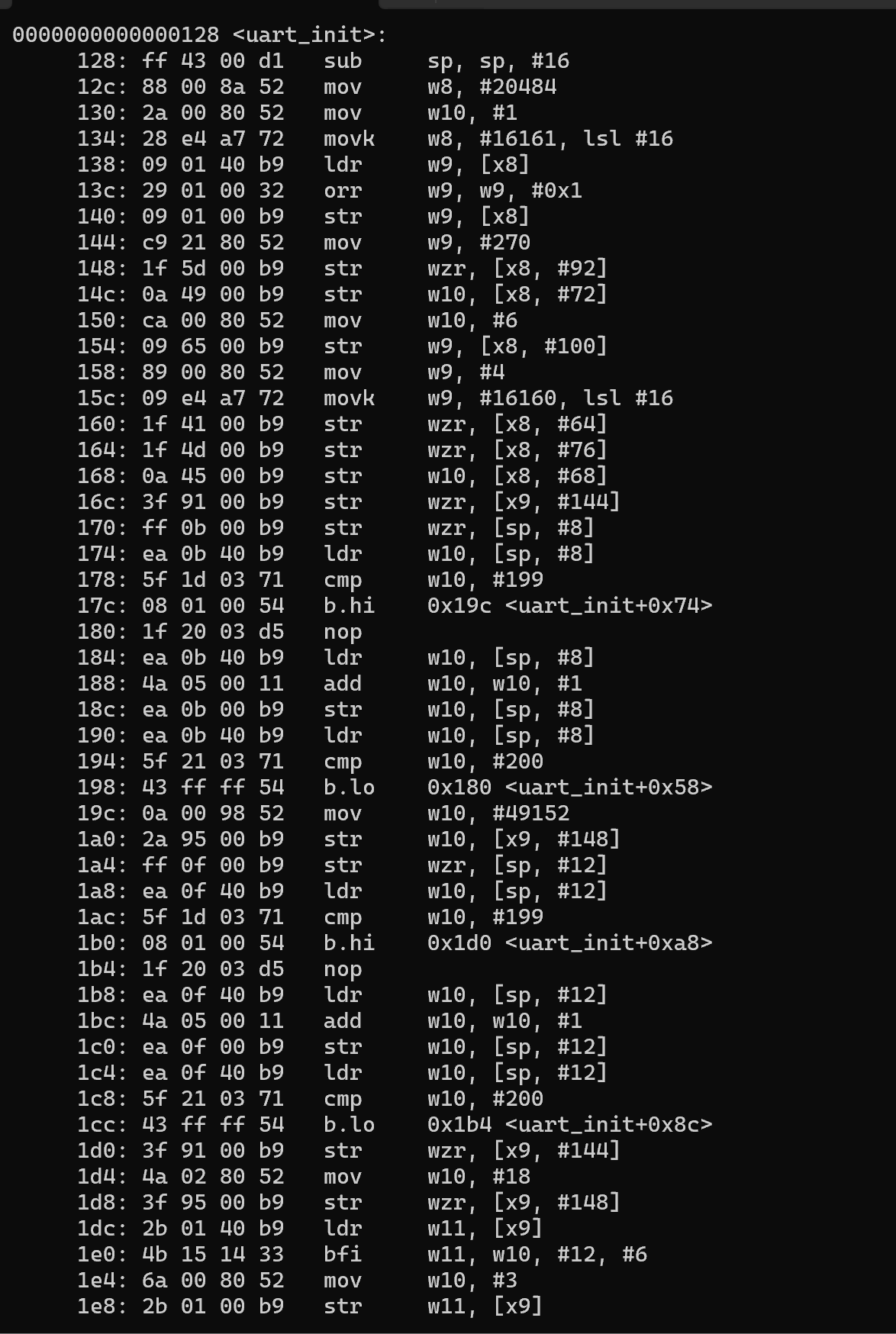
Alright, we see all of the functions we need, and their constituent components, including our NOP. Awesome. Now we need our main file to call our UART functions.
In main.c:
//function prototypes for the UART functionsvoid uart_init(void);void uart_puts(const char *str); void kernel_main(void){ uart_init(); uart_puts("successful connection\r\n"); while (1) { }}void kernel_main(unsigned long inital_value) //inital_value in x0//function prototypes for the UART functionsvoid uart_init(void);void uart_puts(const char *str); void kernel_main(void){//sub sp, sp, #16 -> move 16 bytes down the stack, moving sp down//str x0, [sp, #8] -> stores 42 at sp+8//ldr x8, [sp, #8] -> loads 42 from memory at sp+8 into x8//str x8, [sp] -> x8 into stack memory volatile unsigned long counter = inital_value; //stored on stack while (1){ //<kernel_main+0x14> jumps to here counter++; //load value from stack into x8 add 1 to x8, store //x8 in stack memory } uart_init(); uart_puts("successful connection\r\n"); while (1) { }}
Okay, let's compile both of these:
clang --target=aarch64-none-elf -ffreestanding -fno-stack-protector -O0 -c main.c -o main.o clang --target=aarch64-none-elf -ffreestanding -fno-stack-protector -O0 -c uart.c -o uart.o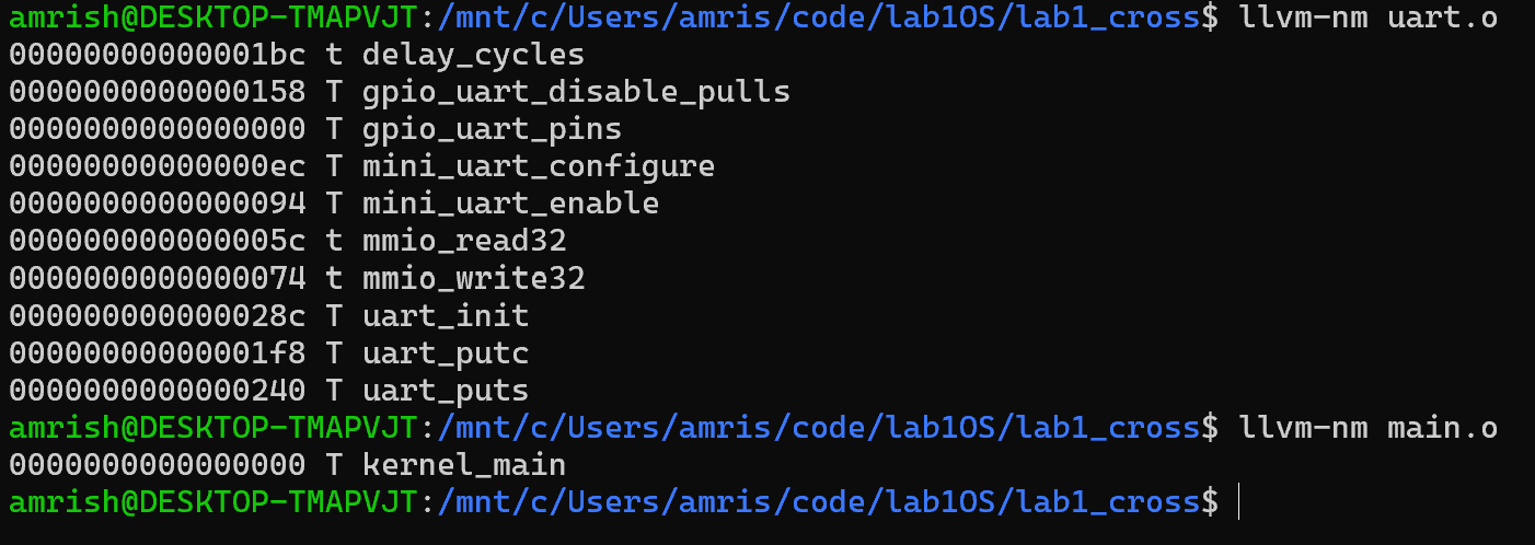
Looks like all the functions we expect to be there. We can also see how big each function is by its offset compared to the offset of the prior function.
Let's prep our linker for real.
nano linker.ld ENTRY(_start) /* we declare where we want to start*/ SECTIONS { /*beginning memory address*/ . = 0x80000; /*our text section*/ .text : { KEEP(*(.text.boot)) /*rest of exe code */ *(.text*) } . = ALIGN(16); .rodata : { *(.rodata*) } . = ALIGN(16); .data : { *(.data*) } . = ALIGN(16); .bss (NOLOAD) : { __bss_start = .; *(.bss*) *(COMMON) __bss_end = .; } . = ALIGN(16); .stack (NOLOAD): { . = ALIGN(16); /* save the address*/ __stack_bottom = .; . += 4096; /*push it 4kb*/ __stack_top = .; /*snag that thang again. now we have the top and bottom *to reference*/ } } ENTRY(_start) /* we declare where we want to start*/ SECTIONS { /*beginning memory address*/ . = 0x80000; /*our text section*/ .text : { KEEP(*(.text.boot)) /*rest of exe code */ *(.text*) } . = ALIGN(16); .rodata : { *(.rodata*) } . = ALIGN(16); .data : { *(.data*) } . = ALIGN(16); .bss (NOLOAD) : { __bss_start = .; *(.bss*) *(COMMON) __bss_end = .; } . = ALIGN(16); .stack (NOLOAD): { . = ALIGN(16); /* save the address*/ __stack_bottom = .; . += 4096; /*push it 4kb*/ __stack_top = .; /*snag that thang again. now we have the top and bottom *to reference*/ } }We needed to add the sections because we now have the real components of a program. We have strings that need to be placed in .rodata, initialized numbers that need to go in .data, and uninitialized data variables. .bss reserves memory without including a separate collection of zero bytes in the boot image. It is our responsibility to initialize that memory to zero before the C code runs.
Now, we need to link the boot, main, linker, and UART into our kernel8.elf file.
clang --target=aarch64-none-elf -ffreestanding -c boot.S -o boot.o ld.lld -m aarch64elf -T linker.ld -o kernel8.elf boot.o main.o uart.o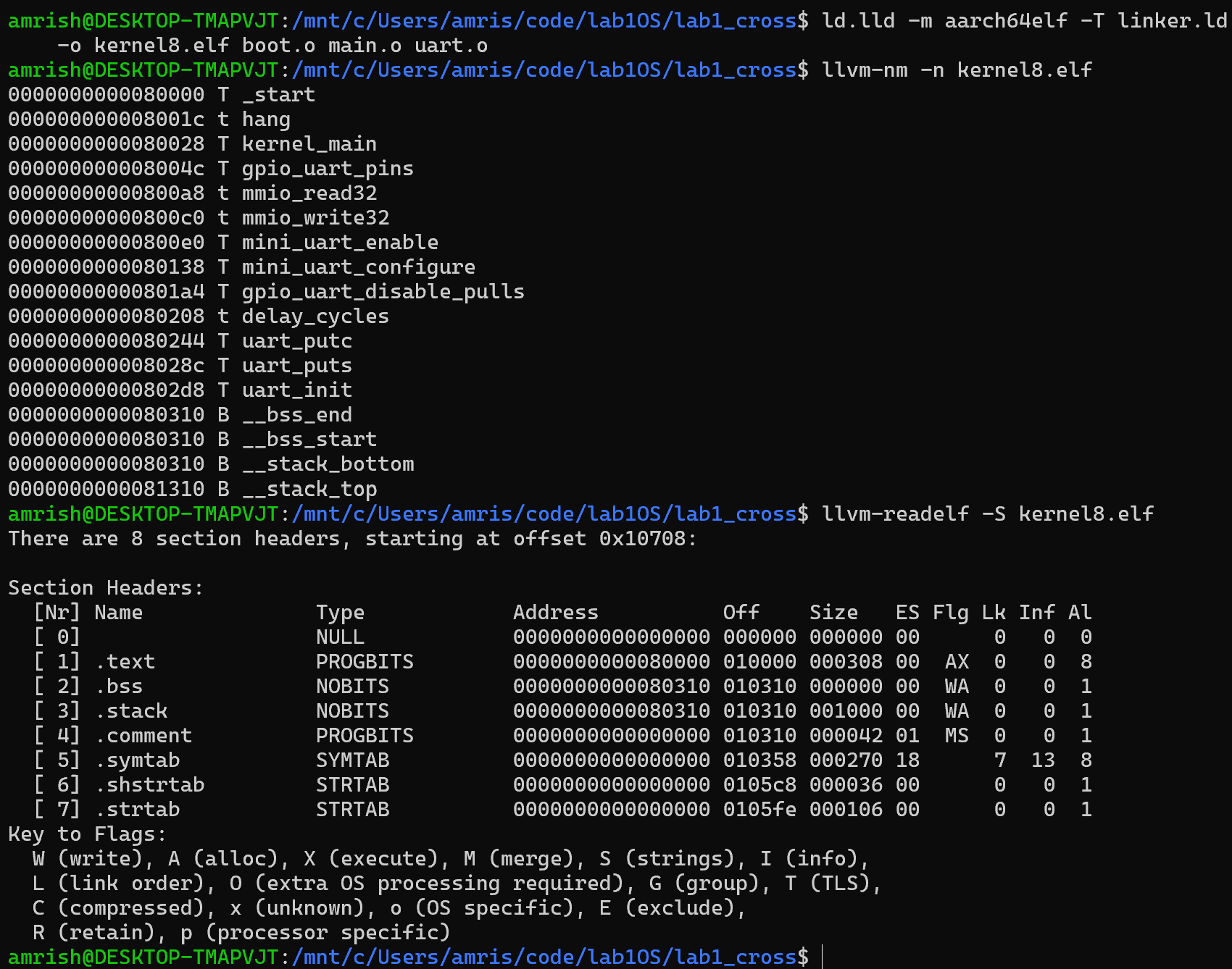
If you're really eagle-eyed, you'll notice .bss end and start are the same address. That's because I wrote the changes in my Obsidian text editor and didn't write them to the disk, so there wasn't actually anything to put in the .bss section.
Alright, let's recompile main:
clang --target=aarch64-none-elf -ffreestanding -fno-stack-protector -O0 -c main.c -o main.oNow we're seeing what we expect.

Now, before we boot, we need to ensure zero-initialized variables are actually zero before we call kernel_main().
In boot.S:
.section .text.boot, "ax" //we need an executable code section .global _start //this is our entry point _start: //we should do this before initializing the stack mrs x1, mpidr_el1 and x1, x1, #0xFF //we want the lowest 8 bits cbnz x1, hang //end this kid's career if he isn't 0 ldr x0, =__stack_top mov sp, x0 ldr x0, =__bss_start ldr x1, =__bss_endclear_bss: cmp x0, x1 b.hs bss_done //branch to bss_done if x0 >= x1 strb wzr, [x0], #1 //store 0 at x0 mem address, inc x0 by 1 b clear_bss bss_done: bl kernel_main hang: wfe b hang .section .text.boot, "ax" //we need an executable code section .global _start //this is our entry point _start: //we should do this before initializing the stack mrs x1, mpidr_el1 and x1, x1, #0xFF //we want the lowest 8 bits cbnz x1, hang //end this kid's career if he isn't 0 cbnz x1, hang //end this kid's career if he isn't 0 ldr x0, =__stack_top mov sp, x0 ldr x0, =__bss_start ldr x1, =__bss_endclear_bss: cmp x0, x1 b.hs bss_done //branch to bss_done if x0 >= x1 strb wzr, [x0], #1 //store 0 at x0 mem address, inc x0 by 1 b clear_bss bss_done: bl kernel_main hang: wfe b hang mov x0, #42 //hello world without "Hello World!" bl kernel_main //branch with link to kernel main hang: b hang //this label just branches to itself, infinitelyWe removed our toy hang procedure and added a couple of things. In start, we put the bss start and end addresses in x0 and x1.
The clear bss procedure clears memory starting at the address in x0 and jumps to bss_done when it's done, which just enters our C program.
Now let's recompile and generate our boot image.
clang --target=aarch64-none-elf -ffreestanding -c boot.S -o boot.o clang --target=aarch64-none-elf -ffreestanding -fno-stack-protector -O0 -c main.c -o main.o clang --target=aarch64-none-elf -ffreestanding -fno-stack-protector -O0 -c uart.c -o uart.o ld.lld -m aarch64elf -T linker.ld -o kernel8.elf boot.o main.o uart.o llvm-objcopy -O binary kernel8.elf kernel8.imgAnd let's take a look at it.
ls -lh kernel8.imgxxd -g 1 -l 32 kernel8.img
Now, the existing Raspberry Pi infrastructure does a lot of heavy lifting for us, so we are going to utilize that and just hijack the loader.
Let's flash Raspberry Pi OS Lite, 64-bit.
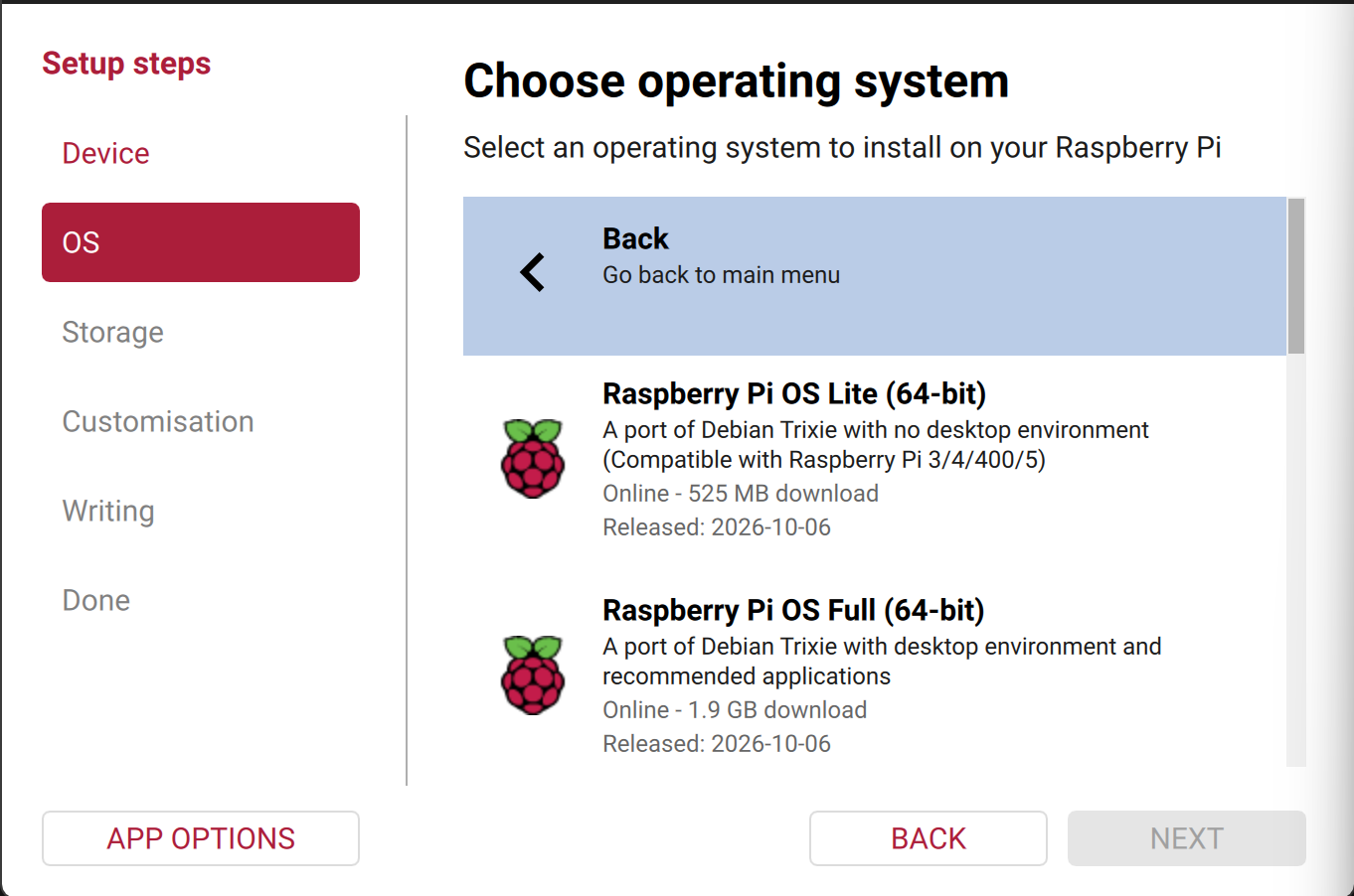
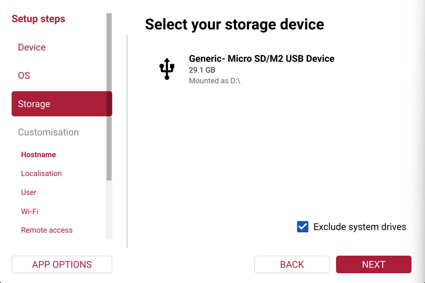
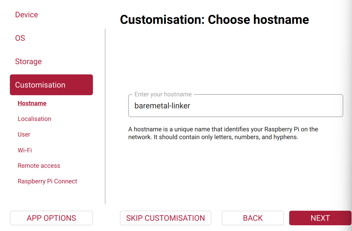
The rest of the configuration options don't matter, since we are lobotomizing it. We just want the boot firmware.
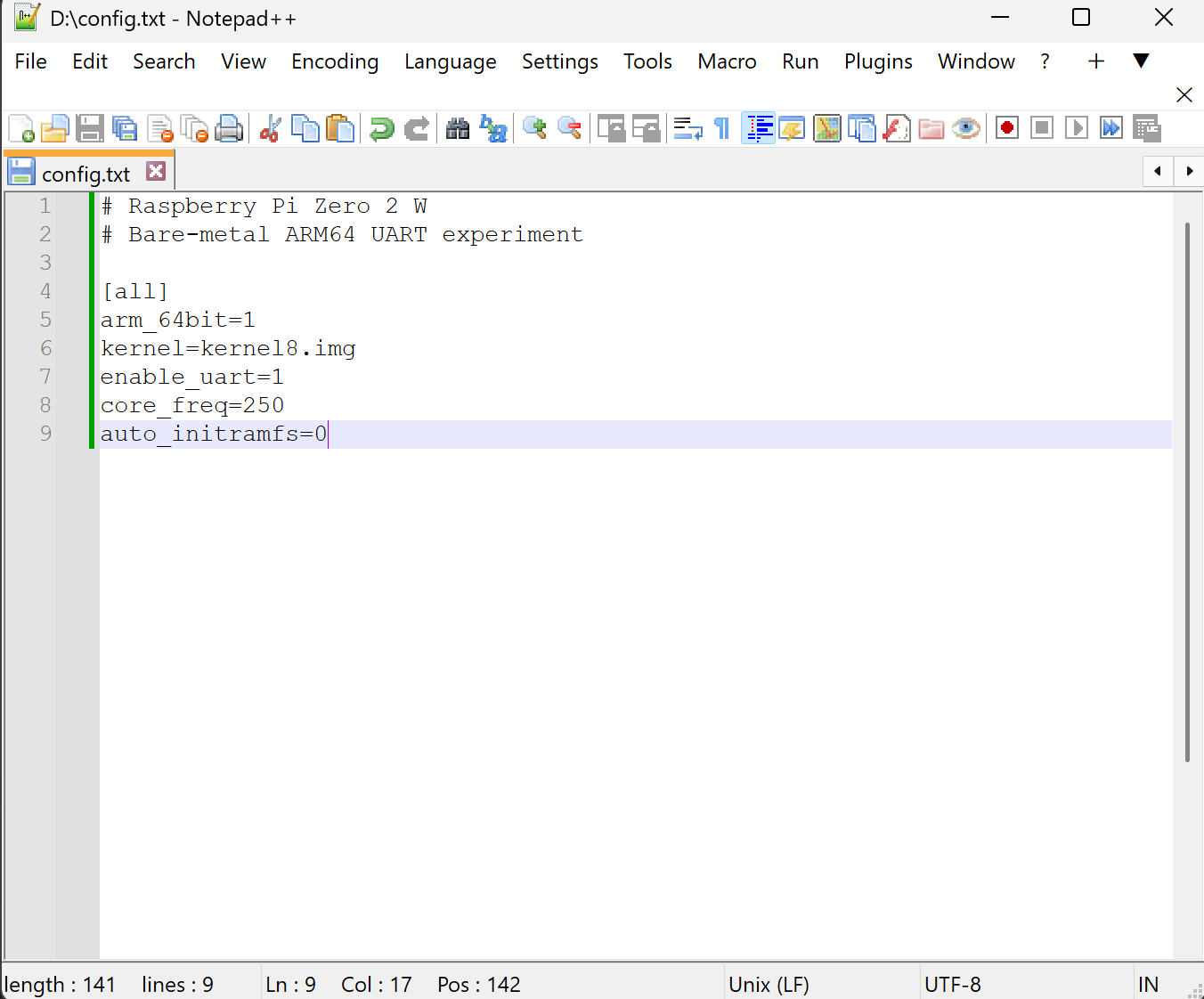
Now, once the SD card is flashed, we need to go to bootfs/config.txt and add a couple of things under the [all] section. We will add:
[all]arm_64bit=1kernel=kernel8.imgenable_uart=1core_freq=250auto_initramfs=0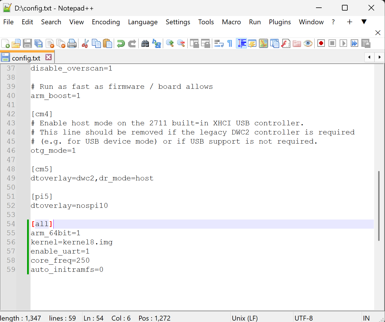
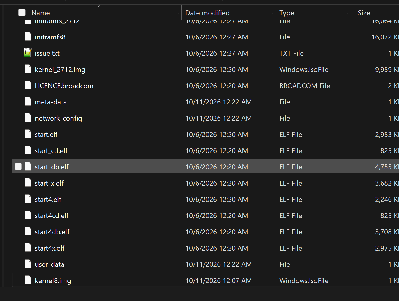
Now replace the ~9,000 KB kernel8.img with ours, which should be around 1 KB.
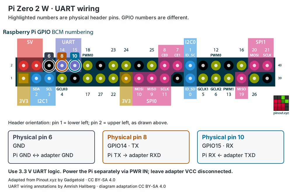
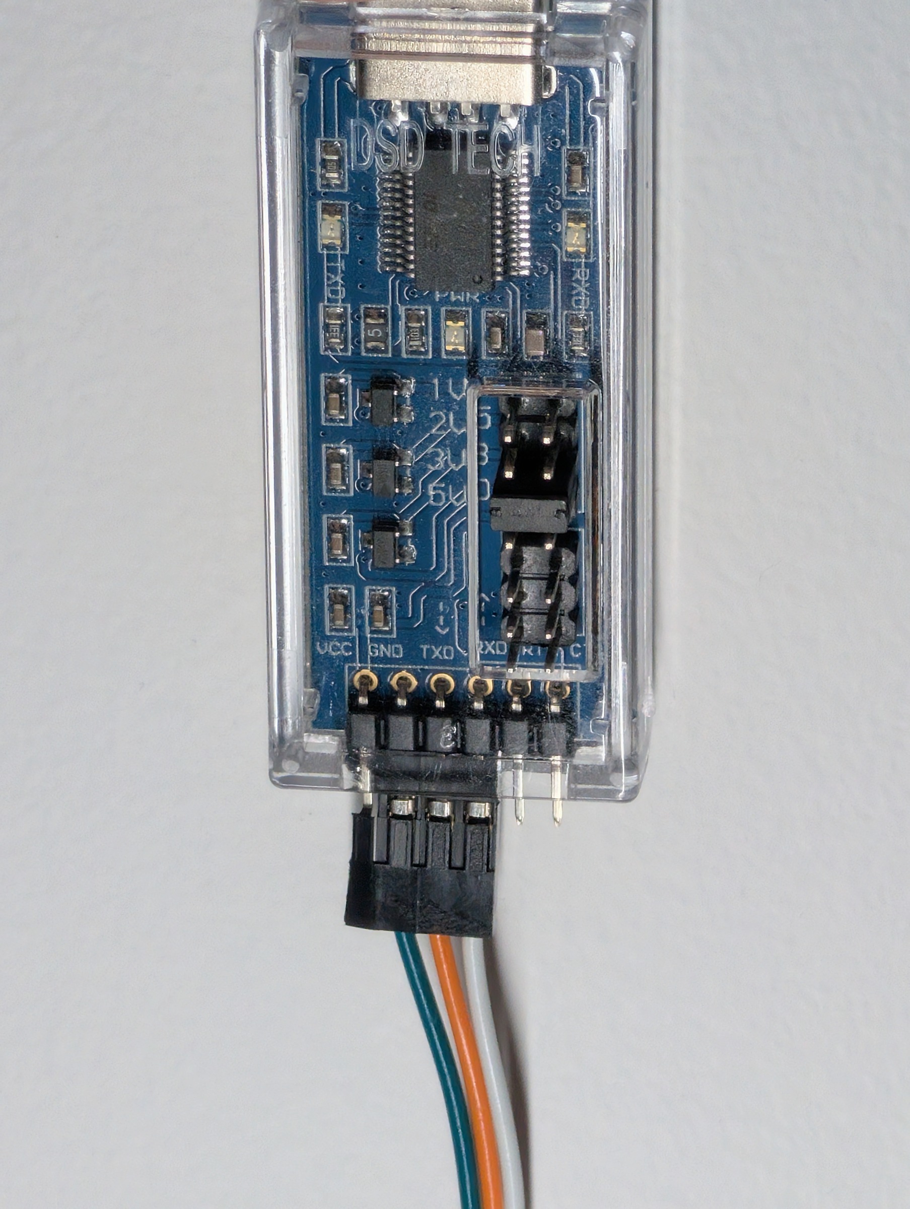
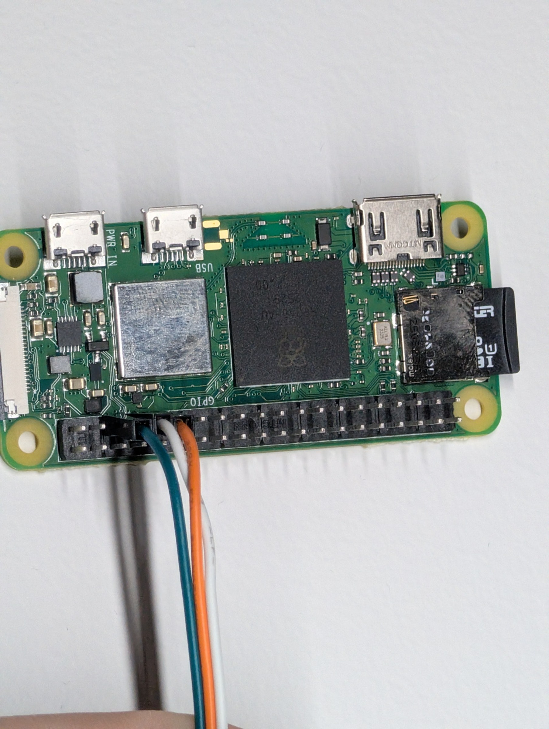
Alright, let's find the COM port. I'm on Windows so I'm going to use PowerShell. Angrily.
Get-PnpDevice -Class Ports -PresentOnly | Select-Object FriendlyName, Status
Now we need to get something ready to listen to the serial connection. I will be using PuTTY.
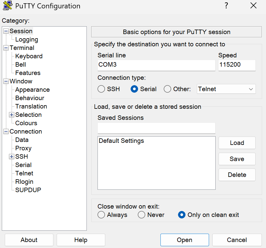
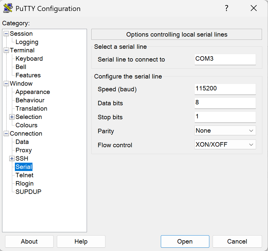
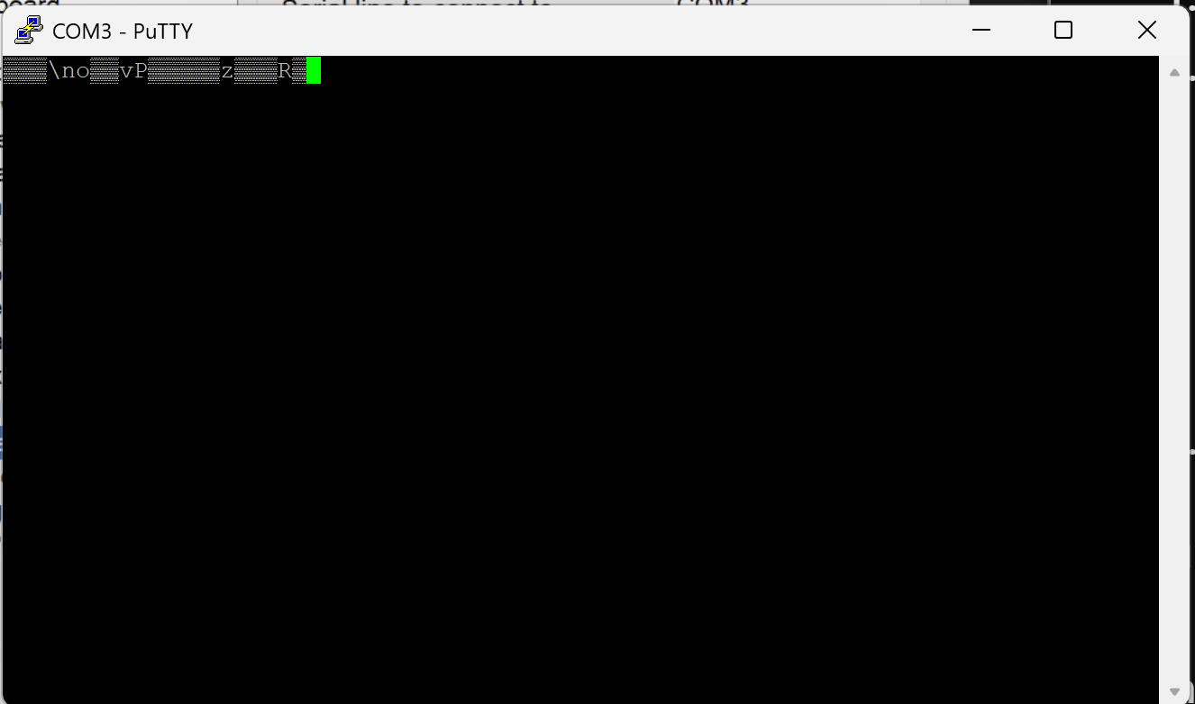
Welp. You're a better man than me if you can read that. The most likely suspect is a mismatched baud rate.
Alright, we need to diagnose our initialization, so let's replace our "successful connection" with 0x55 to make an alternating bit pattern. In this case it's "UUUUUUUUUUUUUUUU".
In main.c:
//function prototypes for the UART functionsvoid uart_init(void);void uart_puts(const char *str); void kernel_main(void){ uart_init(); uart_puts("UUUUUUUUUUUUUUUU\r\n"); while (1) { }}//function prototypes for the UART functionsvoid uart_init(void);void uart_puts(const char *str); void kernel_main(void){ uart_init(); uart_puts("successful connection\r\n"); uart_puts("UUUUUUUUUUUUUUUU\r\n"); while (1) { }}clang --target=aarch64-none-elf -ffreestanding -c boot.S -o boot.o clang --target=aarch64-none-elf -ffreestanding -fno-stack-protector -O0 -c main.c -o main.o ld.lld -m aarch64elf -T linker.ld -o kernel8.elf boot.o main.o uart.o llvm-objcopy -O binary kernel8.elf kernel8.img
Looks like we got what we want.
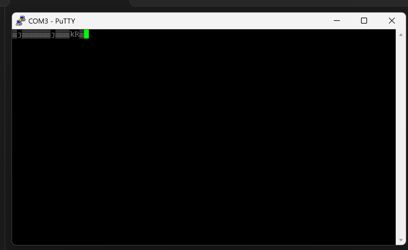

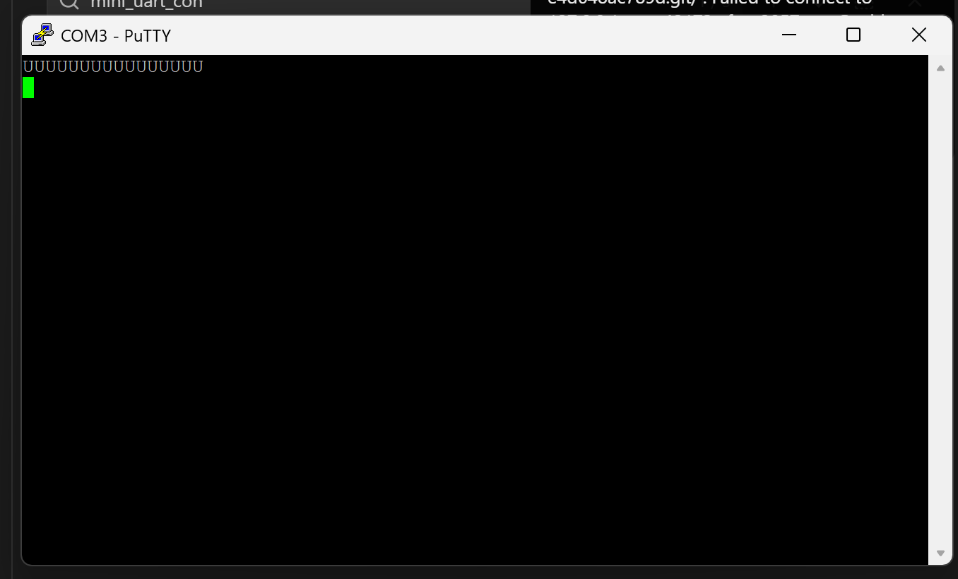
I found I had set AUX_MU_LCR to 1 instead of 3. Upon fixing that and reflashing, the output was readable.
Alright, let's get this working with our more polished output.
In main.c:
//function prototypes for the UART functionsvoid uart_init(void);void uart_puts(const char *str); void kernel_main(void){ uart_init(); uart_puts("successful connection\r\n"); while (1) { }}//function prototypes for the UART functionsvoid uart_init(void);void uart_puts(const char *str); void kernel_main(void){ uart_init(); uart_puts("UUUUUUUUUUUUUUUU\r\n"); uart_puts("successful connection\r\n"); while (1) { }}And in uart.c:
#include <stdint.h> #define AUX_BASE 0x3F215000UL#define AUX_MU_LCR (AUX_BASE + 0x4CUL) //8-bit characters#define AUX_MU_BAUD (AUX_BASE + 0x68UL) // 115200 baud rate#define AUX_ENABLES (AUX_BASE + 0X04UL) //enable mini UART#define AUX_MU_CNTL (AUX_BASE +0X60UL) //lever for tx and rx#define AUX_MU_IER (AUX_BASE + 0x44UL) //interrupt enable#define AUX_MU_IIR (AUX_BASE + 0x48UL) //FIFO control#define AUX_MU_MCR (AUX_BASE + 0x50UL) //modem control#define AUX_MU_IO (AUX_BASE + 0x40UL) // data register, sends to tx FIFO#define AUX_MU_LSR (AUX_BASE + 0x54UL) //line status register #define GPIO_BASE 0x3F200000UL#define GPFSEL1 (GPIO_BASE + 0x04UL)#define GPPUD (GPIO_BASE + 0x94UL)#define GPPUDCLK0 (GPIO_BASE + 0x98UL) static uint32_t mmio_read32(uintptr_t address){ return *(volatile uint32_t *)address;} static void mmio_write32(uintptr_t address, uint32_t value){ *(volatile uint32_t *)address = value; } void gpio_uart_pins(void){ uint32_t selector = mmio_read32(GPFSEL1); selector &= ~((7U << 12) | (7U << 15)); selector |= (2u << 12) | (2u << 15); mmio_write32(GPFSEL1, selector);} void mini_uart_enable(void){ uint32_t value = mmio_read32(AUX_ENABLES); value |= (1u << 0); mmio_write32(AUX_ENABLES, value); mmio_write32(AUX_MU_CNTL,0U); } void mini_uart_configure(void){ mmio_write32(AUX_MU_LCR, 3u); //write the 8-bit mode mmio_write32(AUX_MU_BAUD, 270u); //set the baud to 115200 @ 250 MHz //we're gonna poll instead of using interrupts mmio_write32(AUX_MU_IER, 0u); //no UART interrupts mmio_write32(AUX_MU_MCR, 0u); //no modem mmio_write32(AUX_MU_IIR, 6u); //clear all the rx tx FIFOs } static void delay_cycles(void){ for (volatile unsigned i = 0; i < 200; i++) { __asm__ volatile("nop"); }} void gpio_uart_disable_pulls(void){ mmio_write32(GPPUD, 0u); //disable pull-up and pull-down resistors delay_cycles(); //add our 200 nops mmio_write32(GPPUDCLK0, (1u << 14) | (1u << 15)); //configure GPIO 14 and 15 delay_cycles(); mmio_write32(GPPUD, 0u); //Clear control reg mmio_write32(GPPUDCLK0, 0u); //clear clock reg} void uart_putc(char c){ while ((mmio_read32(AUX_MU_LSR) & (1u << 5)) == 0u) { } //just continuously polling until it's ready mmio_write32(AUX_MU_IO, (uint8_t)c); //send the character, cast to 8 bit uint} char uart_getc(void){ while ((mmio_read32(AUX_MU_LSR) & (1u << 0)) == 0u) { //polling } return (char)(mmio_read32(AUX_MU_IO) & 0xFFu);} //this is effectively our printf alternativevoid uart_puts(const char *str){ while (*str != '\0') { uart_putc(*str); str++; }} //now we need an initialization function void uart_init(void){ mini_uart_enable(); mini_uart_configure(); gpio_uart_disable_pulls(); gpio_uart_pins(); mmio_write32(AUX_MU_CNTL, 3u); //enable tx and rx} #include <stdint.h> #define AUX_BASE 0x3F215000UL#define AUX_MU_LCR (AUX_BASE + 0x4CUL) //8-bit characters#define AUX_MU_BAUD (AUX_BASE + 0x68UL) // 115200 baud rate#define AUX_ENABLES (AUX_BASE + 0X04UL) //enable mini UART#define AUX_MU_CNTL (AUX_BASE +0X60UL) //lever for tx and rx#define AUX_MU_IER (AUX_BASE + 0x44UL) //interrupt enable#define AUX_MU_IIR (AUX_BASE + 0x48UL) //FIFO control#define AUX_MU_MCR (AUX_BASE + 0x50UL) //modem control#define AUX_MU_IO (AUX_BASE + 0x40UL) // data register, sends to tx FIFO#define AUX_MU_LSR (AUX_BASE + 0x54UL) //line status register #define GPIO_BASE 0x3F200000UL#define GPFSEL1 (GPIO_BASE + 0x04UL)#define GPPUD (GPIO_BASE + 0x94UL)#define GPPUDCLK0 (GPIO_BASE + 0x98UL) static uint32_t mmio_read32(uintptr_t address){ return *(volatile uint32_t *)address;} static void mmio_write32(uintptr_t address, uint32_t value){ *(volatile uint32_t *)address = value; } void gpio_uart_pins(void){ uint32_t selector = mmio_read32(GPFSEL1); selector &= ~((7U << 12) | (7U << 15)); selector |= (2u << 12) | (2u << 15); mmio_write32(GPFSEL1, selector);} void mini_uart_enable(void){ uint32_t value = mmio_read32(AUX_ENABLES); value |= (1u << 0); mmio_write32(AUX_ENABLES, value); mmio_write32(AUX_MU_CNTL,0U); } void mini_uart_configure(void){ mmio_write32(AUX_MU_LCR, 3u); //write the 8-bit mode mmio_write32(AUX_MU_BAUD, 270u); //set the baud to 115200 @ 250 MHz //we're gonna poll instead of using interrupts mmio_write32(AUX_MU_IER, 0u); //no UART interrupts mmio_write32(AUX_MU_MCR, 0u); //no modem mmio_write32(AUX_MU_IIR, 6u); //clear all the rx tx FIFOs } static void delay_cycles(void){ for (volatile unsigned i = 0; i < 200; i++) { __asm__ volatile("nop"); }} void gpio_uart_disable_pulls(void){ mmio_write32(GPPUD, 0u); //disable pull-up and pull-down resistors delay_cycles(); //add our 200 nops mmio_write32(GPPUDCLK0, (1u << 14) | (1u << 15)); //configure GPIO 14 and 15 delay_cycles(); mmio_write32(GPPUD, 0u); //Clear control reg mmio_write32(GPPUDCLK0, 0u); //clear clock reg} void uart_putc(char c){ while ((mmio_read32(AUX_MU_LSR) & (1u << 5)) == 0u) { } //just continuously polling until it's ready mmio_write32(AUX_MU_IO, (uint8_t)c); //send the character, cast to 8 bit uint} char uart_getc(void){ while ((mmio_read32(AUX_MU_LSR) & (1u << 0)) == 0u) { //polling } return (char)(mmio_read32(AUX_MU_IO) & 0xFFu);} //this is effectively our printf alternativevoid uart_puts(const char *str){ while (*str != '\0') { uart_putc(*str); str++; }} //now we need an initialization function void uart_init(void){ mini_uart_enable(); mini_uart_configure(); gpio_uart_disable_pulls(); gpio_uart_pins(); mmio_write32(AUX_MU_CNTL, 3u); //enable tx and rx}Now in main.c:
void uart_init(void);void uart_putc(char c);void uart_puts(const char *str);char uart_getc(void); void kernel_main(void){ uart_init(); uart_puts("UART echo is ready\r\n"); while (1) { char c = uart_getc(); if (c == '\r') { uart_puts("\r\n"); } else { uart_putc(c); } }}//function prototypes for the UART functionsvoid uart_init(void);void uart_putc(char c);void uart_puts(const char *str);char uart_getc(void); void kernel_main(void){ uart_init(); uart_puts("successful connection\r\n"); uart_puts("UART echo is ready\r\n"); while (1) { char c = uart_getc(); if (c == '\r') { uart_puts("\r\n"); } else { uart_putc(c); } }}Now we gotta recompile.
clang --target=aarch64-none-elf -ffreestanding -c boot.S -o boot.o clang --target=aarch64-none-elf -ffreestanding -fno-stack-protector -O0 -c main.c -o main.o clang --target=aarch64-none-elf -ffreestanding -fno-stack-protector -O0 -c uart.c -o uart.o ld.lld -m aarch64elf -T linker.ld -o kernel8.elf boot.o main.o uart.o llvm-objcopy -O binary kernel8.elf kernel8.img
Copy over the image and get the COM connection alive again.
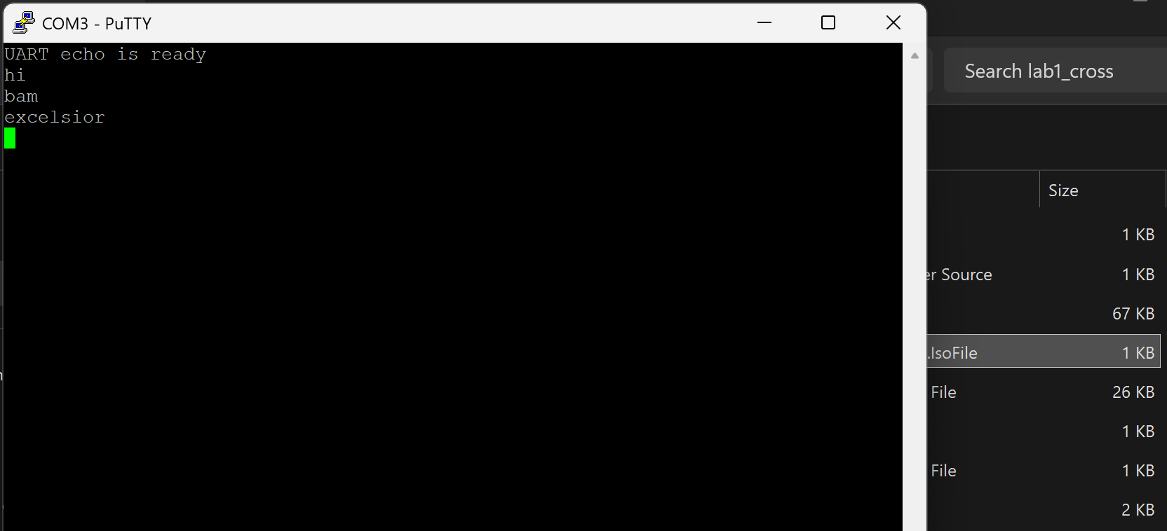
To get the line reader to work, we will need, at minimum, whole lines consumed at a time.
In uart.c:
#include <stdint.h>#include <stddef.h> #define AUX_BASE 0x3F215000UL#define AUX_MU_LCR (AUX_BASE + 0x4CUL) //8-bit characters#define AUX_MU_BAUD (AUX_BASE + 0x68UL) // 115200 baud rate#define AUX_ENABLES (AUX_BASE + 0X04UL) //enable mini UART#define AUX_MU_CNTL (AUX_BASE +0X60UL) //lever for tx and rx#define AUX_MU_IER (AUX_BASE + 0x44UL) //interrupt enable#define AUX_MU_IIR (AUX_BASE + 0x48UL) //FIFO control#define AUX_MU_MCR (AUX_BASE + 0x50UL) //modem control#define AUX_MU_IO (AUX_BASE + 0x40UL) // data register, sends to tx FIFO#define AUX_MU_LSR (AUX_BASE + 0x54UL) //line status register #define GPIO_BASE 0x3F200000UL#define GPFSEL1 (GPIO_BASE + 0x04UL)#define GPPUD (GPIO_BASE + 0x94UL)#define GPPUDCLK0 (GPIO_BASE + 0x98UL) static uint32_t mmio_read32(uintptr_t address){ return *(volatile uint32_t *)address;} static void mmio_write32(uintptr_t address, uint32_t value){ *(volatile uint32_t *)address = value; } void gpio_uart_pins(void){ uint32_t selector = mmio_read32(GPFSEL1); selector &= ~((7U << 12) | (7U << 15)); selector |= (2u << 12) | (2u << 15); mmio_write32(GPFSEL1, selector);} void mini_uart_enable(void){ uint32_t value = mmio_read32(AUX_ENABLES); value |= (1u << 0); mmio_write32(AUX_ENABLES, value); mmio_write32(AUX_MU_CNTL,0U); } void mini_uart_configure(void){ mmio_write32(AUX_MU_LCR, 3u); //write the 8-bit mode mmio_write32(AUX_MU_BAUD, 270u); //set the baud to 115200 @ 250 MHz //we're gonna poll instead of using interrupts mmio_write32(AUX_MU_IER, 0u); //no UART interrupts mmio_write32(AUX_MU_MCR, 0u); //no modem mmio_write32(AUX_MU_IIR, 6u); //clear all the rx tx FIFOs } static void delay_cycles(void){ for (volatile unsigned i = 0; i < 200; i++) { __asm__ volatile("nop"); }} void gpio_uart_disable_pulls(void){ mmio_write32(GPPUD, 0u); //disable pull-up and pull-down resistors delay_cycles(); //add our 200 nops mmio_write32(GPPUDCLK0, (1u << 14) | (1u << 15)); //configure GPIO 14 and 15 delay_cycles(); mmio_write32(GPPUD, 0u); //Clear control reg mmio_write32(GPPUDCLK0, 0u); //clear clock reg} void uart_putc(char c){ while ((mmio_read32(AUX_MU_LSR) & (1u << 5)) == 0u) { } //just continuously polling until it's ready mmio_write32(AUX_MU_IO, (uint8_t)c); //send the character, cast to 8 bit uint} char uart_getc(void){ while ((mmio_read32(AUX_MU_LSR) & (1u << 0)) == 0u) { //polling } return (char)(mmio_read32(AUX_MU_IO) & 0xFFu);} //this is effectively our printf alternativevoid uart_puts(const char *str){ while (*str != '\0') { uart_putc(*str); str++; }} //now we need an initialization function void uart_init(void){ mini_uart_enable(); mini_uart_configure(); gpio_uart_disable_pulls(); gpio_uart_pins(); mmio_write32(AUX_MU_CNTL, 3u); //enable tx and rx} //basically need an interactive terminal size_t uart_readline(char *buffer, size_t capacity){ if (buffer == NULL || capacity == 0) { return 0; } size_t length = 0; while (1) { char c = uart_getc(); if (c == '\r' || c == '\n') { buffer[length] = '\0'; uart_puts("\r\n"); return length; } if (c == '\b' || c == 127) { if (length > 0) { length--; uart_puts("\b \b"); } continue; } if ((unsigned char)c < 32) { continue; } if (length < capacity - 1) { buffer[length++] = c; uart_putc(c); } else { uart_putc('\a'); //buffer is too full } }} #include <stdint.h> #include <stddef.h> #define AUX_BASE 0x3F215000UL#define AUX_MU_LCR (AUX_BASE + 0x4CUL) //8-bit characters#define AUX_MU_BAUD (AUX_BASE + 0x68UL) // 115200 baud rate#define AUX_ENABLES (AUX_BASE + 0X04UL) //enable mini UART#define AUX_MU_CNTL (AUX_BASE +0X60UL) //lever for tx and rx#define AUX_MU_IER (AUX_BASE + 0x44UL) //interrupt enable#define AUX_MU_IIR (AUX_BASE + 0x48UL) //FIFO control#define AUX_MU_MCR (AUX_BASE + 0x50UL) //modem control#define AUX_MU_IO (AUX_BASE + 0x40UL) // data register, sends to tx FIFO#define AUX_MU_LSR (AUX_BASE + 0x54UL) //line status register #define GPIO_BASE 0x3F200000UL#define GPFSEL1 (GPIO_BASE + 0x04UL)#define GPPUD (GPIO_BASE + 0x94UL)#define GPPUDCLK0 (GPIO_BASE + 0x98UL) static uint32_t mmio_read32(uintptr_t address){ return *(volatile uint32_t *)address;} static void mmio_write32(uintptr_t address, uint32_t value){ *(volatile uint32_t *)address = value; } void gpio_uart_pins(void){ uint32_t selector = mmio_read32(GPFSEL1); selector &= ~((7U << 12) | (7U << 15)); selector |= (2u << 12) | (2u << 15); mmio_write32(GPFSEL1, selector);} void mini_uart_enable(void){ uint32_t value = mmio_read32(AUX_ENABLES); value |= (1u << 0); mmio_write32(AUX_ENABLES, value); mmio_write32(AUX_MU_CNTL,0U); } void mini_uart_configure(void){ mmio_write32(AUX_MU_LCR, 3u); //write the 8-bit mode mmio_write32(AUX_MU_BAUD, 270u); //set the baud to 115200 @ 250 MHz //we're gonna poll instead of using interrupts mmio_write32(AUX_MU_IER, 0u); //no UART interrupts mmio_write32(AUX_MU_MCR, 0u); //no modem mmio_write32(AUX_MU_IIR, 6u); //clear all the rx tx FIFOs } static void delay_cycles(void){ for (volatile unsigned i = 0; i < 200; i++) { __asm__ volatile("nop"); }} void gpio_uart_disable_pulls(void){ mmio_write32(GPPUD, 0u); //disable pull-up and pull-down resistors delay_cycles(); //add our 200 nops mmio_write32(GPPUDCLK0, (1u << 14) | (1u << 15)); //configure GPIO 14 and 15 delay_cycles(); mmio_write32(GPPUD, 0u); //Clear control reg mmio_write32(GPPUDCLK0, 0u); //clear clock reg} void uart_putc(char c){ while ((mmio_read32(AUX_MU_LSR) & (1u << 5)) == 0u) { } //just continuously polling until it's ready mmio_write32(AUX_MU_IO, (uint8_t)c); //send the character, cast to 8 bit uint} char uart_getc(void){ while ((mmio_read32(AUX_MU_LSR) & (1u << 0)) == 0u) { //polling } return (char)(mmio_read32(AUX_MU_IO) & 0xFFu);} //this is effectively our printf alternativevoid uart_puts(const char *str){ while (*str != '\0') { uart_putc(*str); str++; }} //now we need an initialization function void uart_init(void){ mini_uart_enable(); mini_uart_configure(); gpio_uart_disable_pulls(); gpio_uart_pins(); mmio_write32(AUX_MU_CNTL, 3u); //enable tx and rx} //basically need an interactive terminal size_t uart_readline(char *buffer, size_t capacity){ if (buffer == NULL || capacity == 0) { return 0; } size_t length = 0; while (1) { char c = uart_getc(); if (c == '\r' || c == '\n') { buffer[length] = '\0'; uart_puts("\r\n"); return length; } if (c == '\b' || c == 127) { if (length > 0) { length--; uart_puts("\b \b"); } continue; } if ((unsigned char)c < 32) { continue; } if (length < capacity - 1) { buffer[length++] = c; uart_putc(c); } else { uart_putc('\a'); //buffer is too full } }}And in main.c:
#include <stddef.h>void uart_init(void);void uart_puts(const char *str);size_t uart_readline(char *buffer, size_t capacity); //don't want to blow our stack sizestatic char input[256]; void kernel_main(void){ uart_init(); uart_puts("terminal ready\r\n"); while (1) { uart_puts("Pi> "); //good as anything? uart_readline(input, sizeof(input)); //more terminal style line now uart_puts("Received: "); uart_puts(input); uart_puts("\r\n"); }} #include <stddef.h>void uart_init(void);void uart_putc(char c);void uart_puts(const char *str);char uart_getc(void);size_t uart_readline(char *buffer, size_t capacity); //don't want to blow our stack sizestatic char input[256]; void kernel_main(void){ uart_init(); uart_puts("UART echo is ready\r\n"); uart_puts("terminal ready\r\n"); while (1) { char c = uart_getc(); if (c == '\r') { uart_puts("\r\n"); } else { uart_putc(c); } uart_puts("Pi> "); //good as anything? uart_readline(input, sizeof(input)); //more terminal style line now uart_puts("Received: "); uart_puts(input); uart_puts("\r\n"); }}
Let's recompile.
clang --target=aarch64-none-elf -ffreestanding -c boot.S -o boot.o clang --target=aarch64-none-elf -ffreestanding -fno-stack-protector -O0 -c main.c -o main.o clang --target=aarch64-none-elf -ffreestanding -fno-stack-protector -O0 -c uart.c -o uart.o ld.lld -m aarch64elf -T linker.ld -o kernel8.elf boot.o main.o uart.o llvm-objcopy -O binary kernel8.elf kernel8.imgCopy the kernel8.img to the Pi's SD card, and plug it into the active COM session.
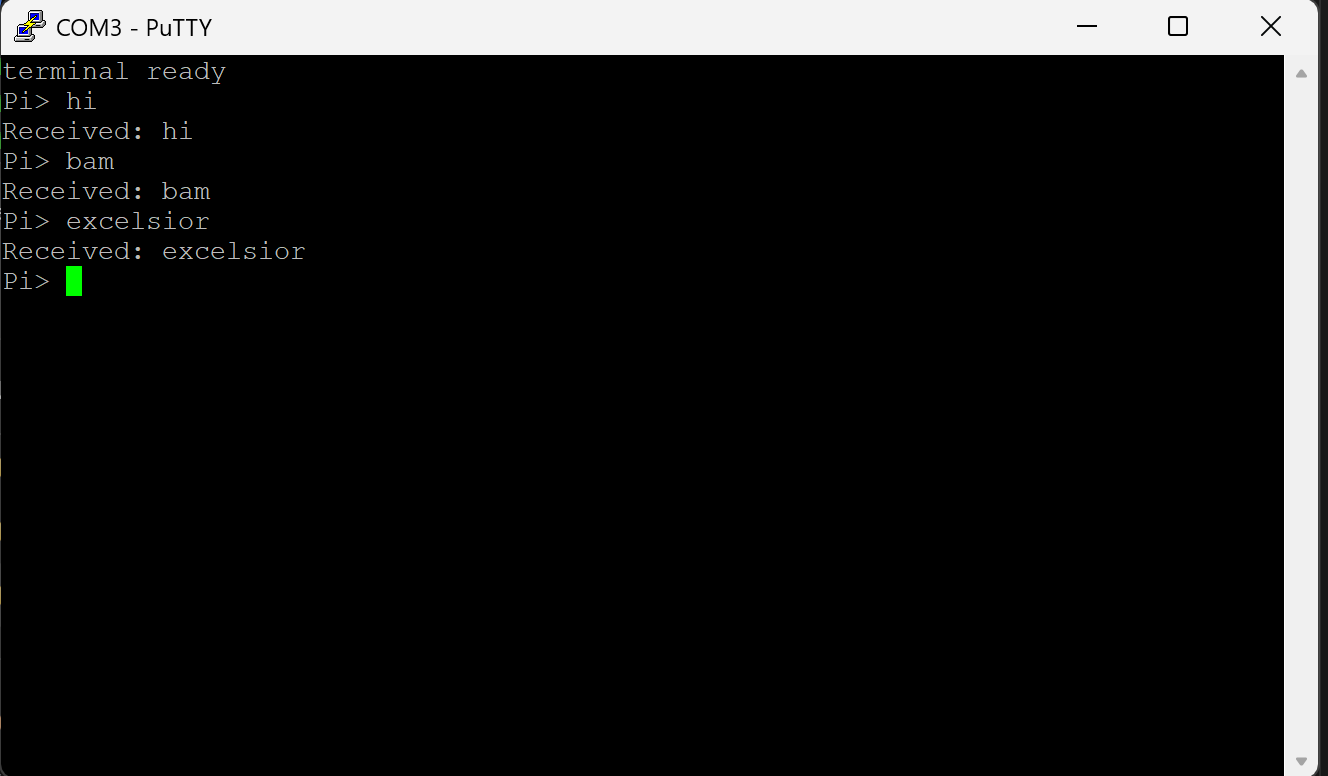
Alright, we have our terminal-like session, which gives us a good jumping off point for all kinds of things we can do on the board, with no OS to cramp our style.
Bare-metal execution and complete system control in this manner have applications in cryptography, cyber-warfare, robotics, electro-optical and electro-explosive controls, real-time targeting, radar processing, etc. If that doesn't trigger childlike excitement in you, you're probably just a simulation.